Buffer Tubes for Mid-Span Storage

a buffer tube and optical fiber technology, applied in the field of optical fiber cables and buffer tubes, can solve the problems of unwanted increases in excess fiber length (efl), attenuation during mid-span storage, etc., and achieve the effects of improving attenuation performance, higher filling coefficient, and high filling coefficien

Active Publication Date: 2010-03-18
DRAKA COMTEQ BV
View PDF97 Cites 98 Cited by
  • Summary
  • Abstract
  • Description
  • Claims
  • Application Information

AI Technical Summary

Benefits of technology

[0011]Accordingly, it is an object of the present invention to provide optical-fiber buffer tubes possessing a higher filling coefficient while ensuring that the optical fibers enclosed therein demonstrate improved attenuation performance when subjected to temperature variations (e.g., between −40° C. and 70° C.).
[0013]It is yet another object of the present invention to provide optical-fiber buffer tubes that include standard single-mode fibers (SSMF) configured in a way that promotes low attenuation.
[0014]It is yet another object of the present invention to provide optical-fiber buffer tubes that include standard single-mode fibers (SSMF) and that are capable of satisfactory mid-span storage over a wide range of temperatures.
[0017]It is yet another object of the present invention to provide optical-fiber buffer tubes that exhibit low post-extrusion shrinkage.

Problems solved by technology

In general, as buffer-tube filling coefficients increase so too does the problem of attenuation during mid-span storage.
In particular, post-extrusion shrinkage, which can occur when a buffer tube is subjected to elevated temperatures, may cause unwanted increases in excess fiber length (EFL).

Method used


Image

  • Buffer Tubes for Mid-Span Storage
  • Buffer Tubes for Mid-Span Storage
  • Buffer Tubes for Mid-Span Storage

Examples


Embodiment Construction

[0025]As noted, the invention embraces an optical-fiber buffer tube having a higher fiber count and yet suitable for deployments requiring mid-span access.

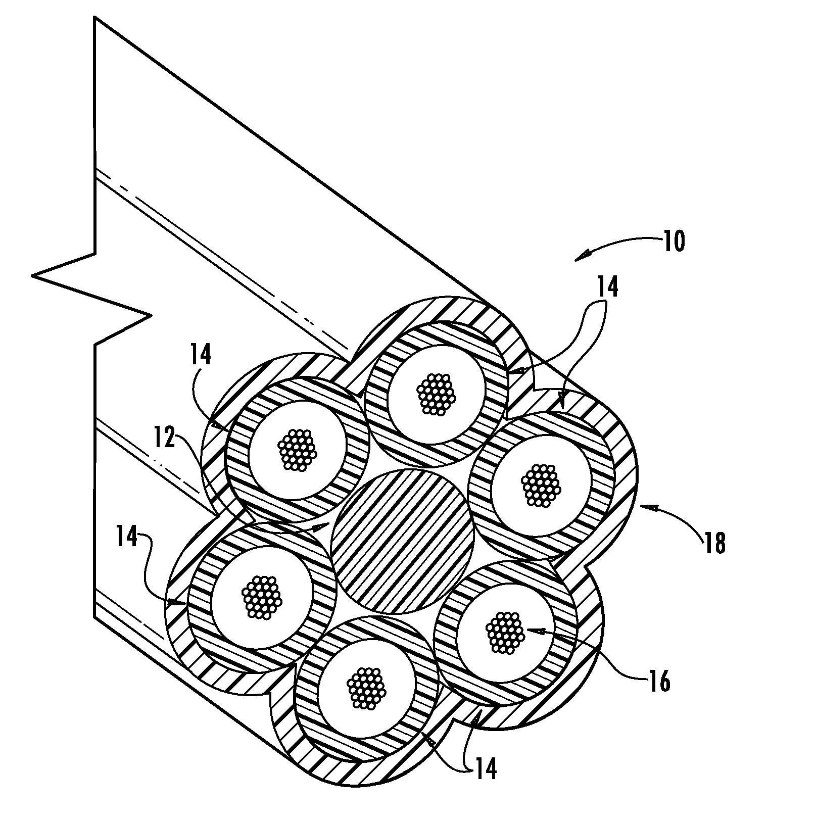
[0026]An exemplary optical-fiber cable includes one or more (e.g., six or so) buffer tubes according to the present invention positioned within a cable jacket (e.g., a polymeric sheath). At least one of the buffer tubes includes a plurality of optical fibers (e.g., 12-24 optical fibers). More typically, each of the buffer tubes positioned within the cable jacket include optical fibers (e.g., six buffer tubes each enclosing 24 optical fibers).

[0027]The optical fibers employed in the buffer tubes according to the present invention are typically conventional standard single-mode fibers (SSMF) possessing diameters of between about 235 microns and 265 microns (i.e., the combined diameter of the glass fiber and its coatings). That said, it is within the scope of the invention to employ optical fibers having smaller diameters (e.g., 200 ...


PUM


Abstract

Disclosed is a buffer tube that possesses a higher buffer-tube filling coefficient. Optical fibers enclosed within the buffer tube demonstrate improved attenuation performance when subjected to temperature variations between about −40° C. and 70° C. The buffer tube is suitable for deployments requiring mid-span access.

Description

CROSS-REFERENCE TO PRIORITY APPLICATIONS[0001]This application claims the benefit of the following commonly assigned applications: U.S. Provisional Application No. 61 / 096,545 (filed Sep. 12, 2008); U.S. Provisional Application No. 61 / 096,750 (filed Sep. 12, 2008); U.S. Provisional Application No. 61 / 113,146 (filed Nov. 10, 2008); and U.S. Provisional Application No. 61 / 139,228 (Dec. 19, 2008). Each of the foregoing patent applications is hereby incorporated by reference in its entirety.FIELD OF INVENTION[0002]The present invention relates to optical-fiber cables and buffer tubes. The present invention, for instance, embraces buffer tubes that are particularly suitable for mid-span deployments.BACKGROUND OF THE INVENTION[0003]As compared with traditional wire-based networks, optical fiber communication networks are capable of transmitting significantly more information at significantly higher speeds. Optical fibers, therefore, are being increasingly employed in communication networks...

Claims


Application Information

Patent Timeline
Patent Type & Authority Applications(United States)
IPC IPC(8): G02B6/44
CPCG02B6/4429G02B6/4434G02B6/4475
Inventor BARKER, JEFFREY SCOTT
Owner DRAKA COMTEQ BV
Why Eureka
Try Eureka