Image forming apparatus

a technology of forming apparatus and forming plate, which is applied in the direction of electrographic process apparatus, instruments, optics, etc., can solve the problems of increased waste toner and decreased transfer rate, and achieve the effect of enhancing the transfer quality of photographs, reducing waste toner, and reducing the resistance of black toner

Active Publication Date: 2010-03-18
KONICA MINOLTA BUSINESS TECH INC
View PDF3 Cites 14 Cited by
  • Summary
  • Abstract
  • Description
  • Claims
  • Application Information

AI Technical Summary

Benefits of technology

[0010]In view of the problems disclosed, an object of the present invention is to provide an image forming apparatus which can properly transfer a toner image onto the second side of a paper sheet without being influenced by a toner image on the first side of the paper sheet.
[0018]According to the first means in the invention, as the transfer voltage output for the second side in an area with overlapped toner images is changed in accordance with the toner adhering amount of the first side, a toner image can properly be transferred onto the second side of the paper sheet without being influenced by the toner image on the first side, and therefore transfer failure such as roughness due to poor transfer output, roughness due to excessive output, and lowered transfer rate can be prevented, so that sufficient images can be formed. Since the transfer rate is high, the waste toner discarded without being transferred onto paper sheets can be decreased.
[0019]According to the second means in the invention, as average values of the toner adhering amounts in the respective image areas are calculated, and the overlap of toner images is detected depending on whether or not any image area on the first side has toner of more than a specified amount, the overlap of toner images can be detected promptly and reliably.
[0023]According to the sixth means in the invention, as the transfer voltage output is changed in the photograph mode, the transfer quality of photographs is enhanced.
[0024]According to the seventh means in the invention, as the resistance of black toner is small in the monochrome mode, it is not necessary to change the transfer voltage output as in the case of the invention, and therefore control can be executed with ease.

Problems solved by technology

Accordingly, it was confirmed that when a transfer voltage was uniformly applied to the area, which contains an image with the toner adhering amount of 7 g / m2 on the first side, so as to obtain an appropriate transfer output, the transfer output became excessive in the area with no image on the first side, resulting in decreased transfer rate and increased waste toner.

Method used


Image

  • Image forming apparatus
  • Image forming apparatus
  • Image forming apparatus

Examples


Embodiment Construction

[0034]Description is now given of the embodiment of the invention with reference to the accompanying drawings.

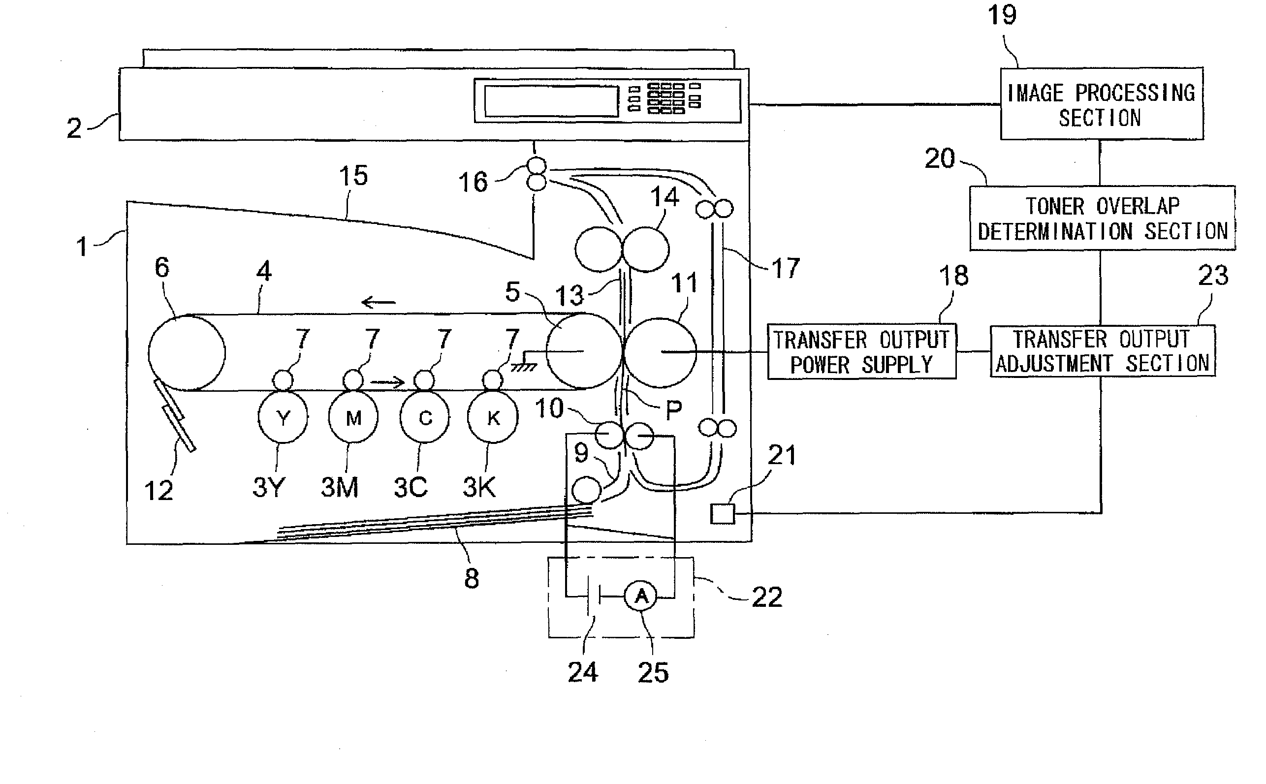
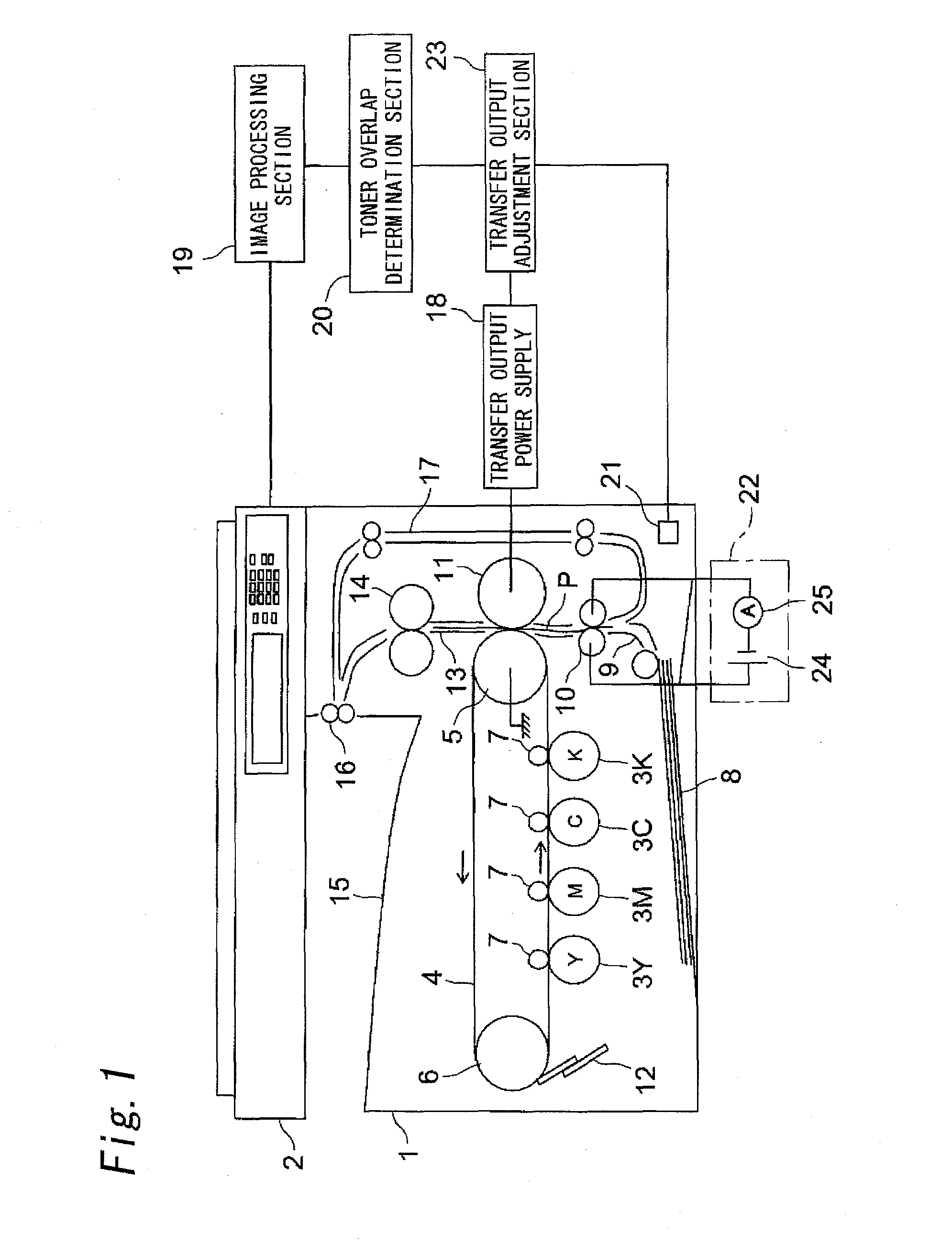
[0035]FIG. 1 shows the simplified structure view of an image forming apparatus embodied in the invention. The image forming apparatus is composed of an image forming section 1 and an image reading section 2.

[0036]In the image forming section 1, image forming units 3Y, 3M, 3C and 3K for forming toner images of respective colors Y (yellow), M (magenta), C (cyan) and K (black) are placed along a straight line portion of an intermediate transfer belt 4.

[0037]The intermediate transfer belt 4, which is stretched over a driving roller 5 and a follower roller 6, can run in an arrow direction.

[0038]Inside the intermediate transfer belt 4, a primary transfer roller 7 is provided so as to face the respective image forming units 3Y and 3M, 3C and 3K across the intermediate transfer belt 4 so that the toner images on the image carriers are transferred onto the intermediate transfer belt ...


PUM


Abstract

A toner image can properly be transferred onto the second side of a paper sheet without being influenced by the toner image on the first side. There are provided a detection unit 20 for detecting overlap of the toner images on the first side and the second side of the paper sheet based on image data, and a transfer output adjustment unit 22 which changes a transfer voltage output for the second side in an area with the overlap of the toner images depending on the toner adhering amount of the first side.

Description

[0001]This application is based on application No. 2008-239533 filed in Japan on Sep. 18, 2008, the contents of which are hereby incorporated by reference.BACKGROUND OF THE INVENTION[0002]The invention relates to an image forming apparatus such as monochrome or color electrophotographic copying machines, printers, facsimiles, and multi-functional machines having these functions.[0003]In an image forming apparatus having an automatic double-sided copy function to form images on both sides of paper sheets, image formation on both the sides of the paper sheets is achieved by the steps of transferring a toner image formed on an image carrier such as photoconductor drums or intermediate transfer bodies onto the first side of a paper sheet in a transfer section, fixing the toner image thereon with a fixing device, feeding the paper sheet again after the paper sheet is reversed, transferring a next image formed on the image carrier onto the second side of the paper sheet, and fixing the im...

Claims


Application Information

Patent Timeline
Patent Type & Authority Applications(United States)
IPC IPC(8): G03G15/00
CPCG03G15/235G03G15/5025G03G2215/1623G03G2215/00776G03G2215/1614G03G2215/00772
Inventor MORI, TOMOHIDE
Owner KONICA MINOLTA BUSINESS TECH INC
Why Eureka
Try Eureka