Fuel cell system, electrode catalyst degradation judgment method, and moving body

Active Publication Date: 2010-03-18
TOYOTA JIDOSHA KK
View PDF2 Cites 14 Cited by
  • Summary
  • Abstract
  • Description
  • Claims
  • Application Information

AI Technical Summary

Benefits of technology

[0017]With this arrangement, if calculated power which can be received is smaller than the set power specified beforehand, then it is determined that the electric storage device or a load of the fuel cell is unable to receive surplus power, and the additional auxiliary device is driven so as to allow surplus power to be consumed by the auxiliary device. This makes it possible to prevent the electric storage device from being overcharged and also to increase the voltage reduction speed, as compared with the case where the auxiliary device is not driven.
[0018]Further, a fuel cell system in accordance with the present invention is a fuel cell system which reduces an output voltage of a fuel cell when carrying out a catalyst activation process, comprising: power calculating means which calculates power which can be received by at least one of an electric storage device and a load of the fuel cell which will be an object receiving surplus power generated by the fuel cell; and voltage conversion controlling means which controls a voltage converter which changes an output voltage of the fuel cell on the basis of the receivable power calculated by the power calculating means, wherein the voltage conversion controlling means limits the output voltage changing speed of the fuel cell as the receivable power calculated by the power calculating means is smaller.
[0019]With this arrangement, when the catalyst activation process is carried out, as the receivable power calculated by the power calculating means is smaller, that is, as the receivable power of at least one of the electric storage device and a load of the fuel cell, which will be an object receiving surplus power generated by the fuel cell, is smaller, the output voltage changing speed of the fuel cell is limited so as to restr

Problems solved by technology

However, the conventional technique does not give consideration to determining the voltage decreasing speed of a fuel cell while giving consideration to surplus power of the fuel cell when carrying out the catalyst activation process of the fuel cell.
Hence, there have been cases where an inconvenience results when activating a catalyst layer of the fuel cell.
For example, increasing the fuel cell voltage reduction speed

Method used


Image

  • Fuel cell system, electrode catalyst degradation judgment method, and moving body
  • Fuel cell system, electrode catalyst degradation judgment method, and moving body
  • Fuel cell system, electrode catalyst degradation judgment method, and moving body

Examples


Embodiment Construction

[0027]The following will describe a fuel cell system in accordance with an embodiment of the present invention with reference to the accompanying drawings. In the present embodiment, the description will be given to an example wherein the present invention has been applied to a vehicle-mounted power generation system of a fuel cell vehicle.

(Explanation of Configuration)

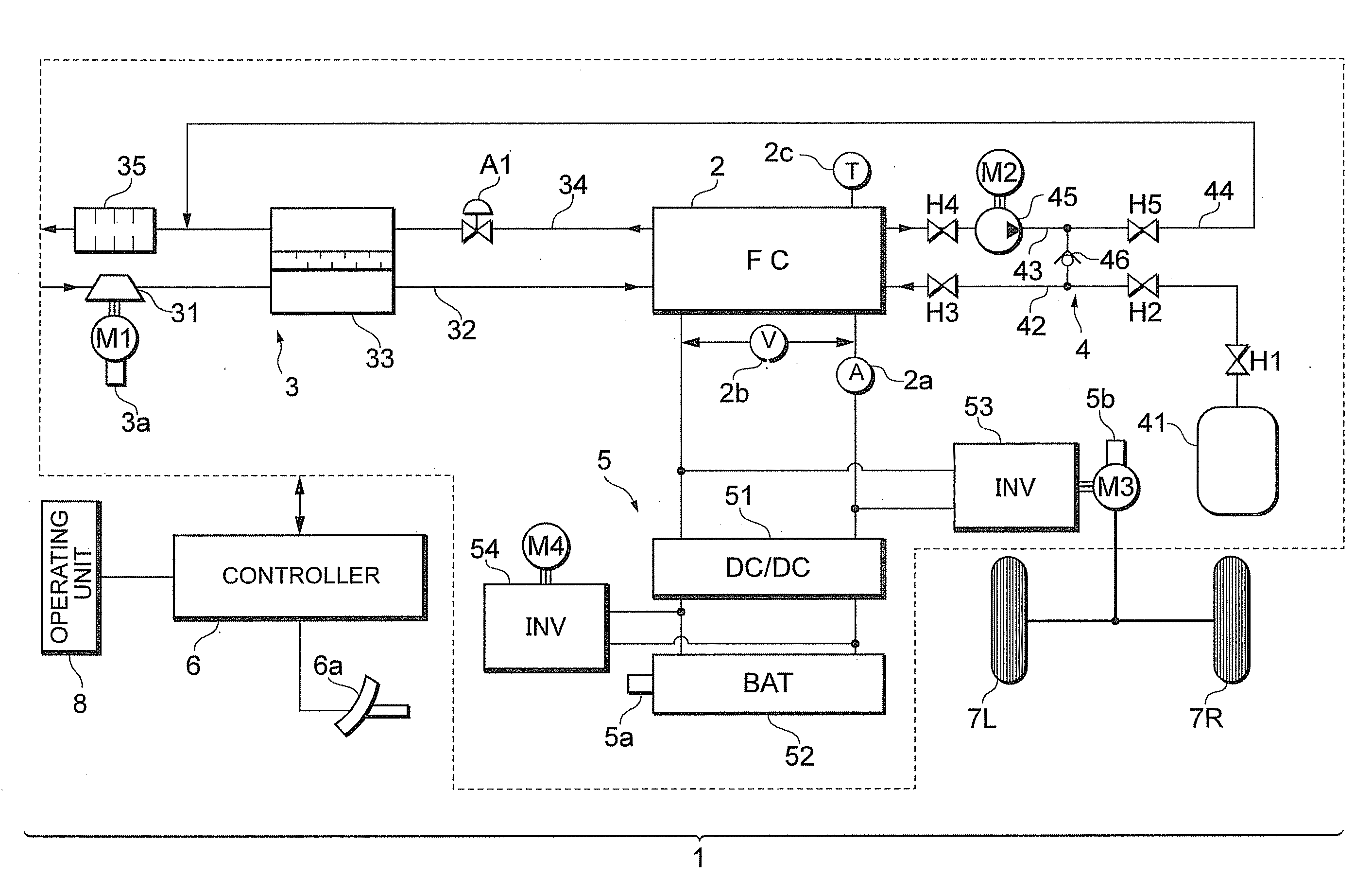
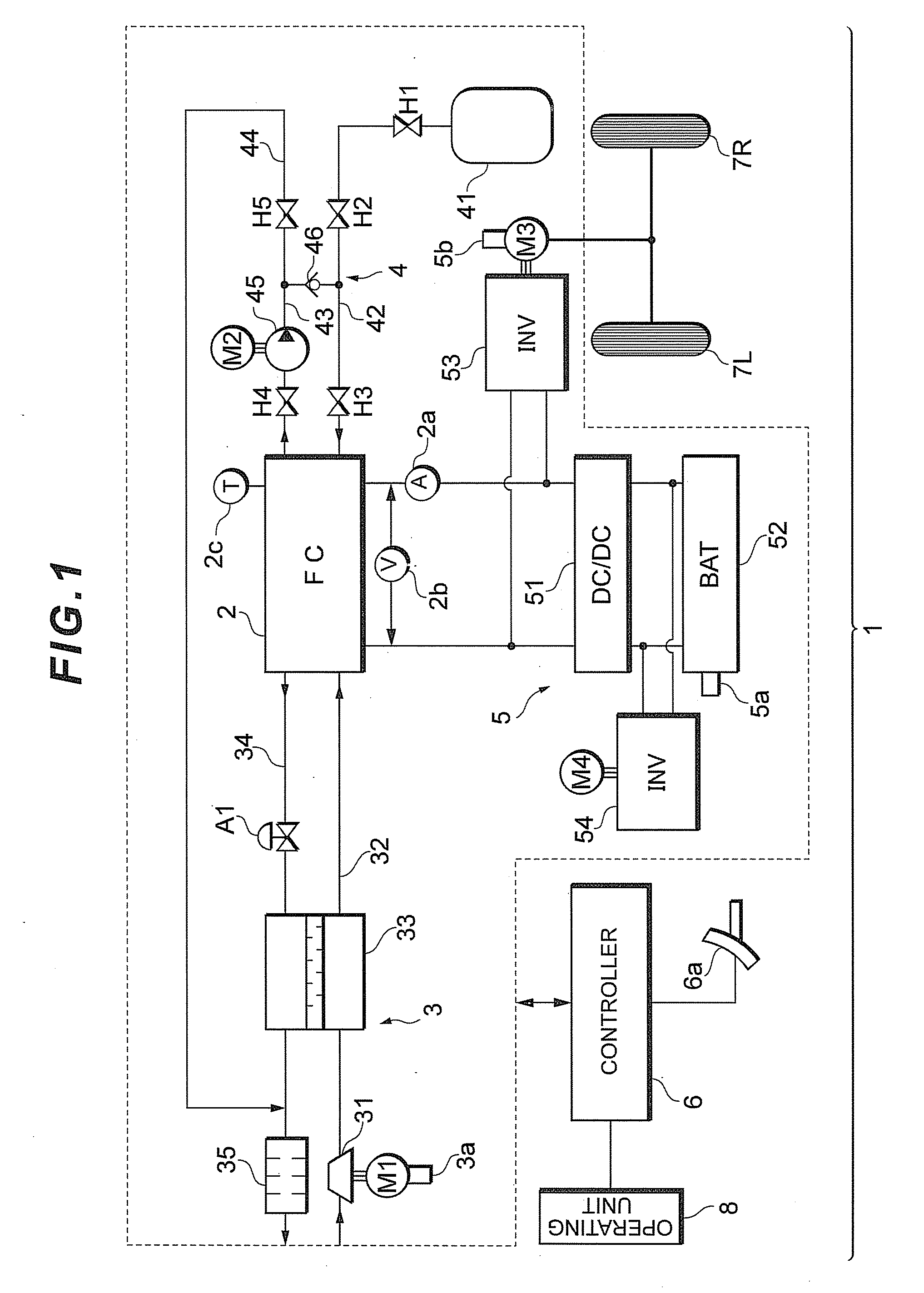
[0028]First, by referring to FIG. 1, the configuration of a fuel cell system 1 in accordance with the embodiment of the present invention will be described.

[0029]As illustrated in FIG. 1, the fuel cell system 1 according to the present embodiment is equipped primarily with a fuel cell 2 which carries out power generation by receiving supplied reactant gases (an oxidizing gas and a fuel gas) and generates power by the power generation, an oxidizing gas piping system 3 which supplies air as the oxidizing gas to the fuel cell 2, a fuel gas piping system 4 which supplies a hydrogen gas as the fuel gas to the fuel cell 2, ...


PUM


Abstract

When an output voltage of a fuel cell is lowered to carry out a catalyst activation process so as to activate a catalyst during an intermittent operation of the fuel cell, if generated power P1 exceeds allowed battery charge power, while generated power P2 does not exceed the allowed battery charge power, then low speed corresponding to the generated power P2 is selected and the output voltage of the fuel cell is decreased toward a target voltage on the basis of the low speed, which has been selected, thereby restraining sudden generation of surplus power caused by a reduction in the output voltage of the fuel cell. By the control described above, a voltage reduction speed of a fuel cell is determined according to a receiving capability of an object which receives surplus power generated by the fuel cell during the catalyst activation process of the fuel cell.

Description

TECHNICAL FIELD[0001]The present invention relates to a fuel cell system and more particularly to a fuel cell system capable of decreasing an output voltage of a fuel cell when carrying out a catalyst activation process.BACKGROUND ART [0002]Hitherto, in a fuel cell system, adsorption of oxygen into a catalyst layer of a fuel cell in operation causes a drop in an output voltage of the fuel cell. In such a case, a process for activating the catalyst layer of a fuel cell stack (i.e., reduction process) is carried out by interrupting the supply of oxygen to the fuel cell and decreasing the power generation voltage of the fuel cell down to a reduced zone of the catalyst layer.[0003]As a technique related to such a catalyst activation process of a fuel cell, there has been proposed, for example, a technique wherein a low-voltage battery is used for an auxiliary device constituting a hybrid fuel cell, and surplus power which increases as voltage decreases during the catalyst activation pro...

Claims


Application Information

Patent Timeline
IPC IPC(8): H01M8/04
CPCH01M8/04238H01M8/04365H01M8/04373H01M8/04559Y02E60/50H01M8/04626H01M8/04679H01M8/04865H01M16/006H01M8/04589Y02E60/10
Inventor UMAYAHARA, KENJIYOSHIDA, MICHIO
Owner TOYOTA JIDOSHA KK
Why Eureka
Try Eureka