
Stackable column assemblies and methods of construction

Active Publication Date: 2010-03-25
COLLINS WILLIAM M
View PDF21 Cites 13 Cited by
  • Summary
  • Abstract
  • Description
  • Claims
  • Application Information

AI Technical Summary

Benefits of technology

[0011]It is an advantage of the present invention that both column load and floor load are transferred from the coupler to the lower column in compression and without welding to the column or the use of through-column apertures.

Problems solved by technology

The alignment is important for load bearing reasons and locating the column in the floor below is often problematic once the floor is in place.
However, this uniformity of column size and shape is often undesirable as the column load of successive floors typically diminishes as the building rises.
If the coupler is attached in shear to the column by through-column bolts, the through-column apertures weaken the column and thus require increased column thickness and / or diameter.
In addition, there are generally alignment problems with the prior art pre-punched apertures which may interfere with the abutting contact needed between the ends of the columns for the transfer of column load in compression.
In addition, there is the risk that aperture misalignment may cause one of the two or more fasteners to take all of the shear load rather than sharing it, leading to successive fastener failure.
If the coupler is attached in shear to the column by welding, such welds typically are overhead welds which are very difficult to make on site.
In addition, welding is possible only if the two metals are sufficiently close together, and the combination of variations manufacturing tolerances as to the size and shape on the columns and coupler may make welding the coupler to the column impossible without the use of filler bars.
Floor loads are often unbalanced, e.g. the floor load is not the same on all four sides of columns at the corners of buildings or adjacent mezzanines.
This result is an eccentricity or bending moment of the coupler about the column.
However, this requires that the beam connectors extend both above and below the top of the lower column and this increases the risk of bending moments as discussed supra.

Method used


Image

  • Stackable column assemblies and methods of construction
  • Stackable column assemblies and methods of construction
  • Stackable column assemblies and methods of construction

Examples


Embodiment Construction

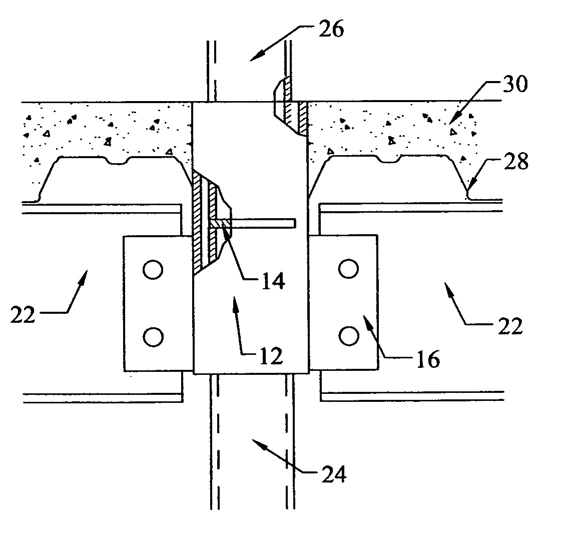
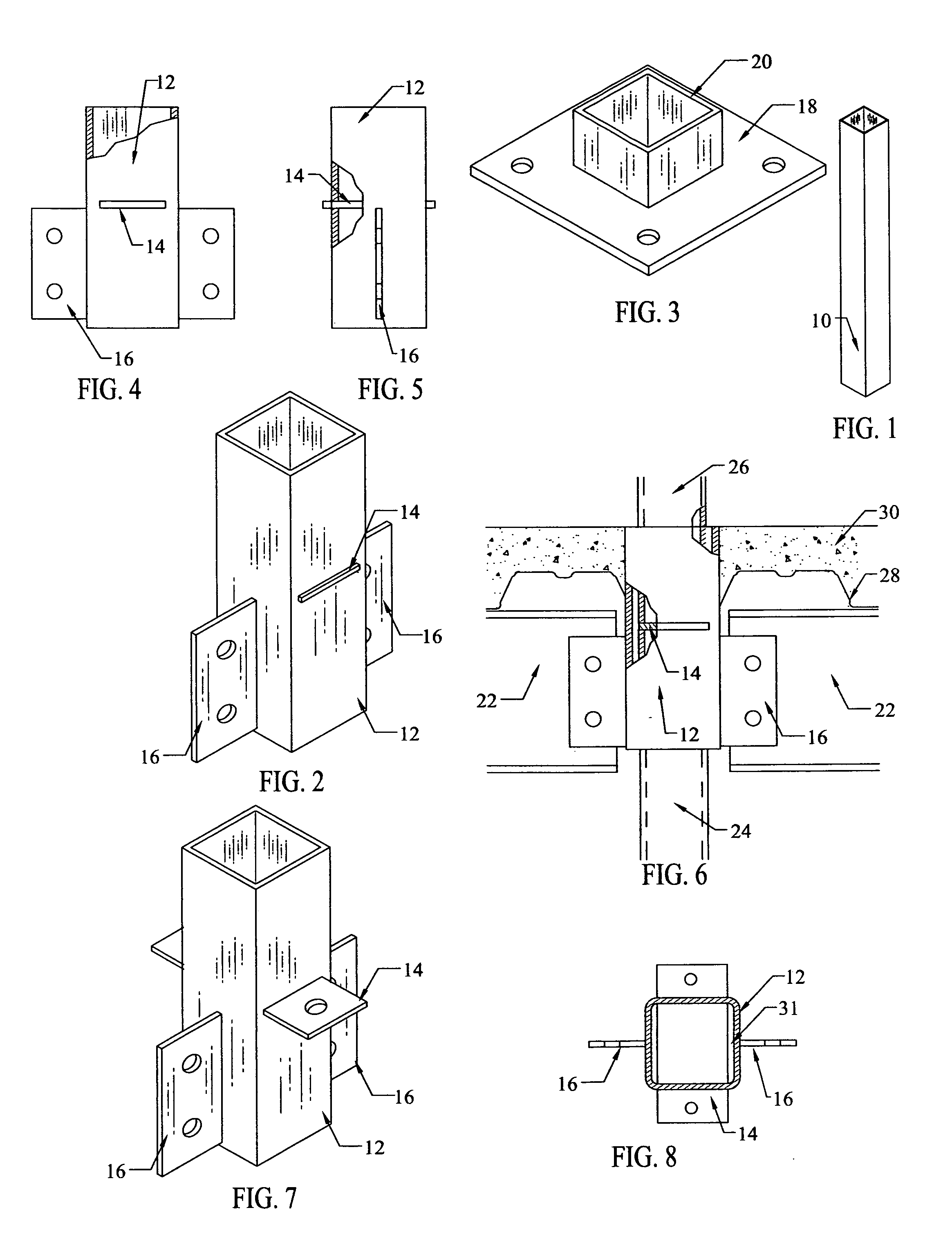
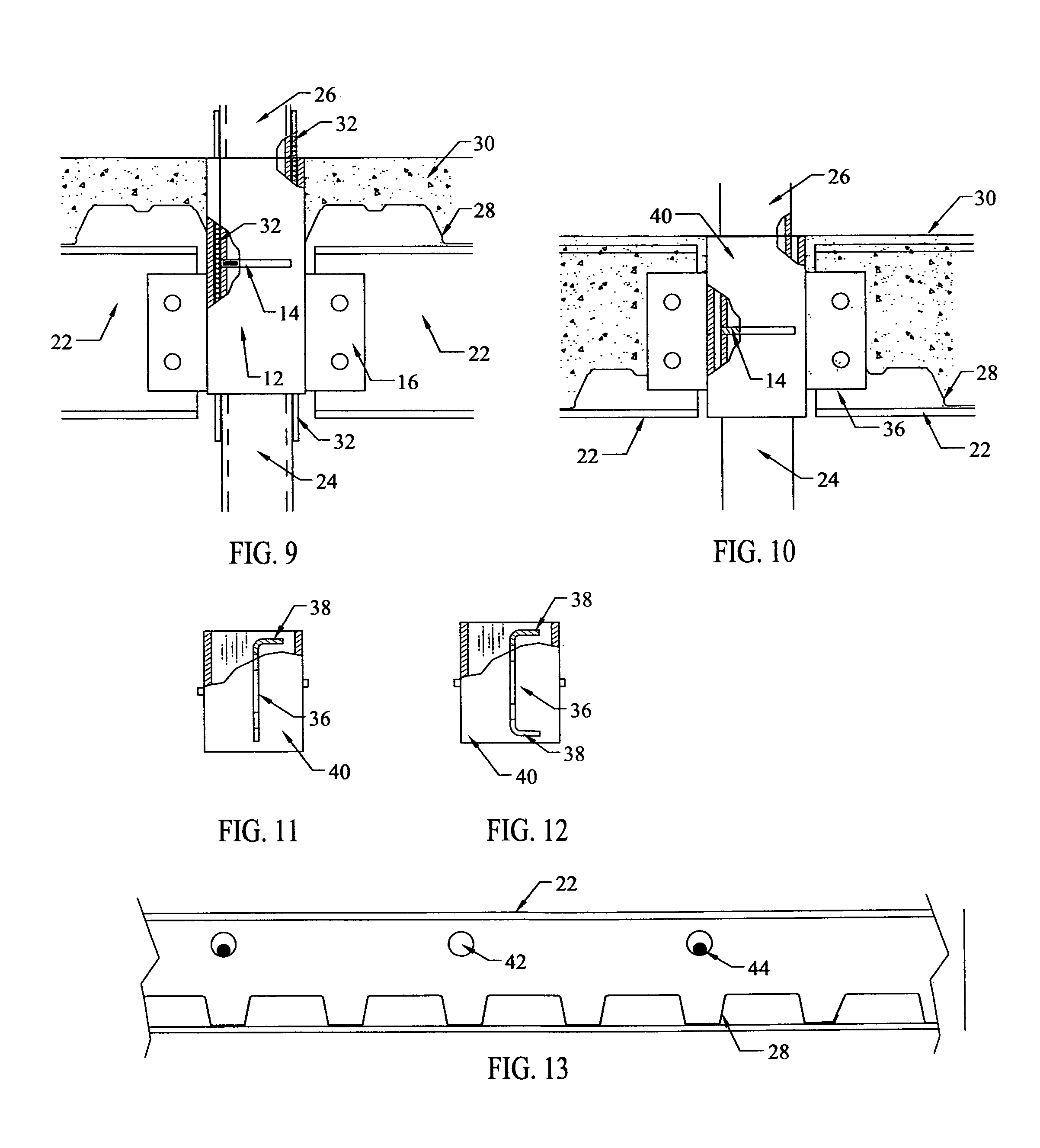
[0037]With reference now to the figures where liked numerals are used to indicate like elements, one embodiment of the column member of the present invention is illustrated in FIG. 1 as being a steel tube 10 having a substantially uniform wall thickness and being generally square in cross-section. The column members may be fabricated in any conventional manner in a desired height, or fabricated and then cut to the desired height.

[0038]One embodiment of the coupler is shown in FIG. 2 and comprises a relatively short section of a column member 12 dimensioned slightly larger than the column member 10 of FIG. 1 to telescopingly receive one end of two column members into opposite ends open ends.

[0039]Coupler 12 is divided intermediate its length at the approximate mid-point thereof by a horizontal plate 14. The coupler 12 may be fabricated by providing horizontal slots in two opposing sides of the coupler through which the plate 14 may be inserted and then welded into place.

[0040]The len...


PUM


Abstract

An improved stackable square tubular column assembly and method of assembly for multi-floor steel-framed buildings in which hollow columns for vertically adjacent floors are joined by a coupler having beam connectors extending outwardly therefrom so that the coupler supports the floor load in shear. The core of the assembly is the coupler having a flat plate extending through horizontal slots in opposing walls of the coupler that divides the coupler into two compartments, each compartment telescopingly receiving the end of a single floor column so that the column load of the upper column is uniformly distributed in compression over the walls of the lower column through the plate. Advantages of the various embodiments include (a) eliminating the necessity of column abutment, (b) eliminating the need for exact registration of the columns, (c) eliminating the need for through-column bolts, (d) eliminating the need for overhead welds, (e) improved tolerances for coupler-to-lower column tolerances, (f) improved resistance to bending or twisting of the coupler about the supporting column, (g) the addition of coupler-to-coupler tension cables, (h) additional support for metal decking, (i) the connection of stacked columns without through-column bolts, (j) coupler length reduction for reduced thickness composite floors without sacrificing resistance to floor load shear, (k) a continuous span for reduced thickness floors, (l) shear panels anchored to the structural steel columns, coupler and beams, and (m) the ability of the coupler to accommodate normal X-bracing and tube bracing.

Description

RELATED APPLICATIONS[0001]This application is a continuation in part of co-pending application Ser. No. 11 / 512,168 filed Aug. 30, 2006, the content thereof is hereby incorporated herein by reference.BACKGROUND OF THE INVENTION[0002]The present invention relates to a improved stackable columns used in the construction of multi-floor steel-framed buildings and to methods of constructing such buildings using a stackable column. More particularly, the present invention relates to apparatus and methods of stacking and coupling together hollow vertical columns for supporting successive floors of a multi-floor steel-framed building. As disclosed infra, an integral part of the present invention is a novel coupler.[0003]Multi-floor steel-framed buildings are typically constructed with columns spanning the full height of the building, with intermediate floors framed with structural beams or joints on which a floor is laid. For ease in erection, it is highly desirable to construct each multi-f...

Claims


Application Information

Patent Timeline
IPC IPC(8): E04C3/04E04B1/38
CPCE04B1/24E04B2001/2406E04B2001/2454Y10T403/34E04B2001/2463E04B2001/2484E04B2001/2496E04B2001/246
Inventor COLLINS, WILLIAM M.
Owner COLLINS WILLIAM M
Learn More