Packing material

a technology of packing material and cushioning medium, which is applied in the field of packaging materials, can solve the problems of low cushioning medium efficiency, increase in the amount of check valve material, and inability to allow the cushioning medium to flow backward from the cushioning medium storage portions, etc., and achieves the effect of superior to conventional process cartridge packaging

Inactive Publication Date: 2010-03-25
CANON KK
View PDF9 Cites 29 Cited by
  • Summary
  • Abstract
  • Description
  • Claims
  • Application Information

AI Technical Summary

Benefits of technology

[0004]Thus, the primary object of the present invention is to provide a process cartridge packaging material, which is different from conventional process cartridge packaging materials in the pattern in which a check valve is welded to each of its cushioning medium storage portions, and also, is superior to conventional process cartridge packaging materials, in the efficiency with which cushioning medium can be injected into the cushioning medium storage portions.

Problems solved by technology

Some of these check valves are designed so that they allow the cushioning medium to flow into the cushioning medium storage portions, but, do not allow the cushioning medium to flow backward from the cushioning medium storage portions.
Thus, these check valves are problematic in that they are low in the efficiency with which the cushioning medium is injected into the cushioning medium storage portions.
This means is problematic in that the employment of this means results in increase in the amount of the check valve material, which results in increase in the check valve cost.

Method used


Image

  • Packing material
  • Packing material
  • Packing material

Examples


embodiment 1

Packaging Material Structure

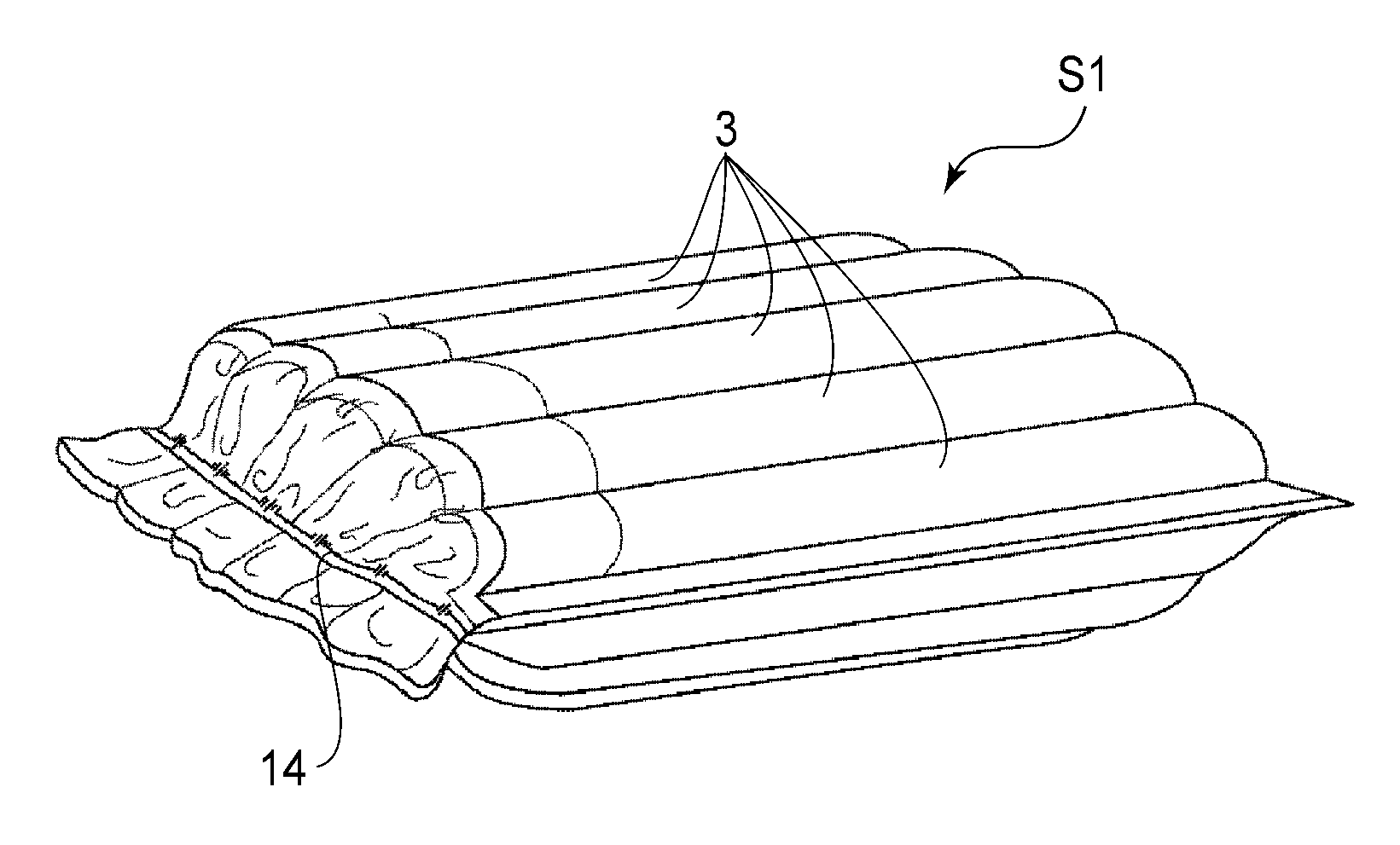
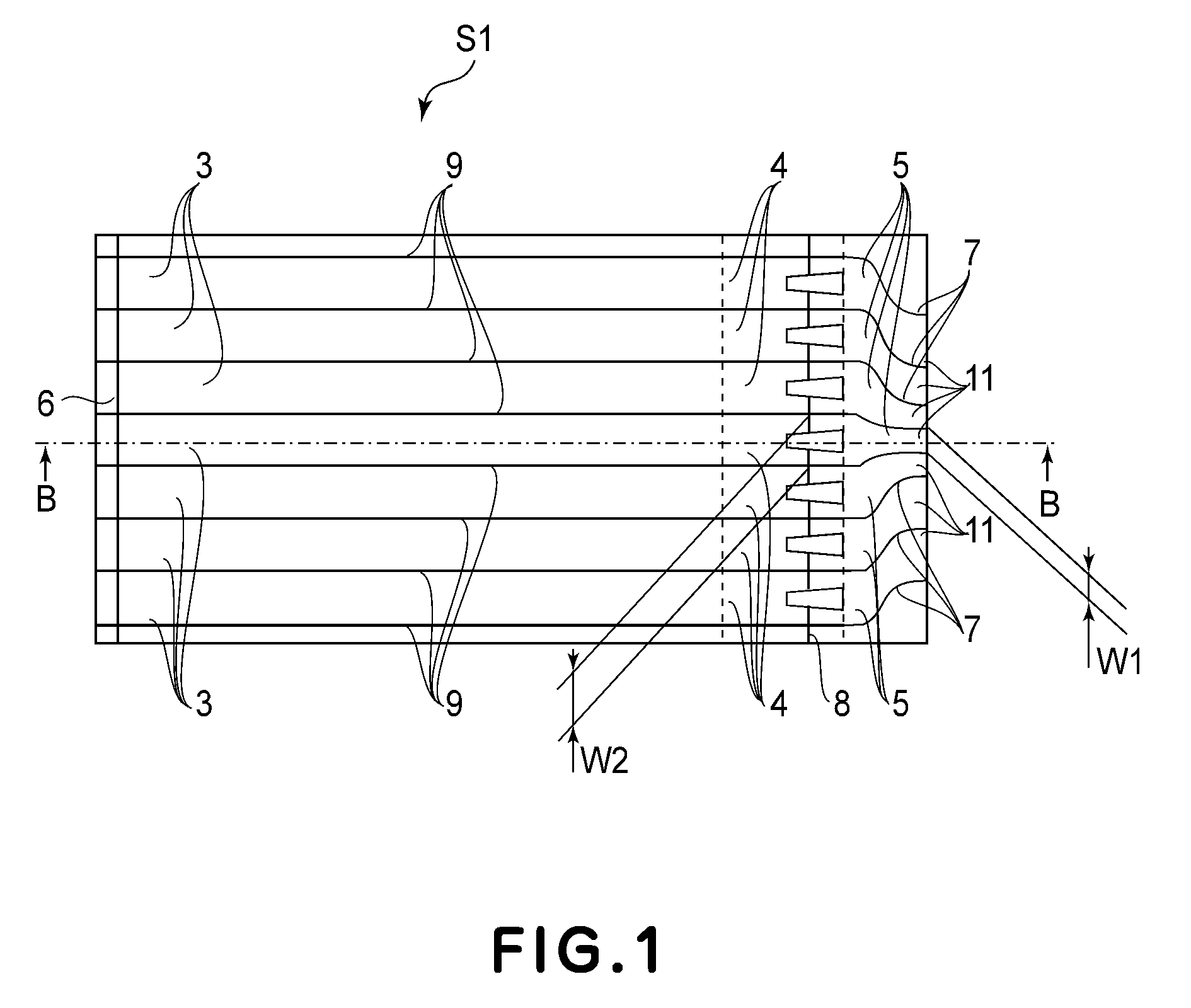
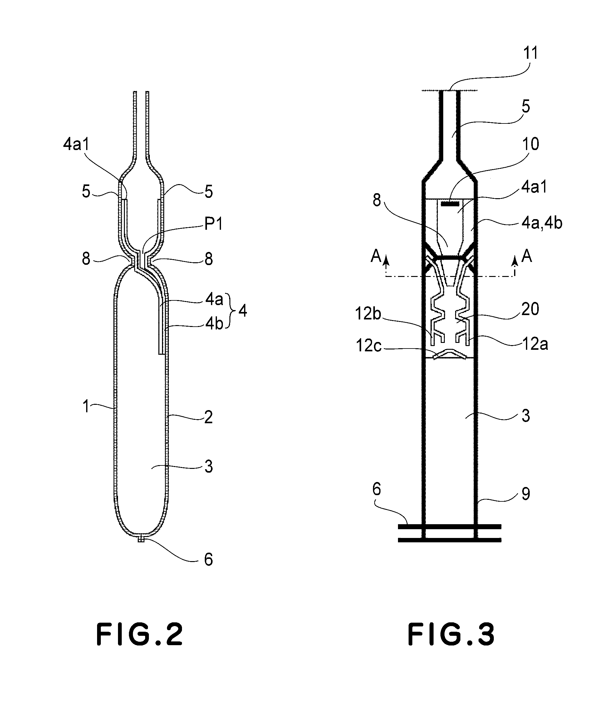
[0031]Referring to FIGS. 1 and 2, a packaging material S1 in this embodiment is made up of two pieces 1 and 2 of flexible plastic film, which are thermally welded in layers. The areas 6, 8, and 9 are the areas of the two films 1 and 2, by which the two films 1 and 2 are welded. The packaging material S1 has multiple cushioning medium storage portions 3, which are placed side by side. Each cushioning medium storage portion 3 is enabled to store cushioning medium, which in this embodiment is air. It is formed by welding the two flexible films 1 and 2 (which hereafter will be referred to simply as films 1 and 2) across the welding areas 8, 6, and 9. It is rectangular, with its longer edges being substantially longer than its shorter edges. Further, each cushioning medium storage portion 3 is separated from the next cushioning medium storage portions by the welding areas 9. One of the lengthwise ends of the packaging material S1 is provided with multiple cush...

embodiment 2

Packaging Material Structure

[0056]In the first preferred embodiment, the check valve 4 had two portions, that is, the top and bottom check valves 4a and 4b. In this embodiment, however, the check valve 4 has only one valve 4d.

[0057]FIG. 11 is a plan of one of the multiple cushioning units of packaging material S1, as seen from the direction perpendicular to the lengthwise direction of the unit. It shows the central cushioning medium entrance 5 and corresponding cushioning medium storage portion 3. FIG. 12 is a sectional view of one of the multiple cushioning units of packaging material S1, shown in FIG. 11, at Plane C-C in FIG. 11, after the introduction of the air into the unit.

[0058]Referring to FIG. 11, the film 2 has the check valve 4d, which was welded in advance to the film 2 by thermally melting the film 2 across welding areas 12a-12c.

[0059]More specifically, referring to FIGS. 11 and 12, when the films 1 and 2 are welded to each other to create the packaging material S, th...

embodiment 3

Packaging Material Structure

[0064]In the first preferred embodiment, there was only one cushioning medium passage 20. The third preferred embodiment is characterized in that each cushioning unit is provided with two cushioning medium passages 21 and 22. Referring to FIGS. 15 and 16, the patterns of the welding areas 24a-24c across which the check valve 4e is thermally welded to the film 2 are such that each cushioning unit is provided with the two cushioning medium passages 21 and 22, which are positioned side by side. However, the central welding area 24b is integration of the welding areas 12a and 12b in the first preferred embodiment, and is shaped as such.

[0065]To describe in more detail, the primary portion 21c of the passage 21 is created by welded portions 24a1, 24a2, 24a6, and 24a10, and welded portions 24b1, 24b2, 24b6, and 24b10. The primary portion 22c of the passage 22 is created by welded portions 24c1, 24c2, 24c6, and 24c10, and welded portions 24b1, 24b2, 24b6, and 24...


PUM


Abstract

A packing member for packing an article, the packing member includes a medium accommodating portion accommodating medium; a non-return valve for passing the medium toward the medium accommodating portion along a longitudinal direction of the medium accommodating portion and for stopping the medium in an opposite direction away from the medium accommodating portion; and a flow path, formed by welding the non-return valve to the medium accommodating portion, for passing the medium, the flow path including a reference flow path portion extending in the longitudinal direction and an expanding flow path portion having a width larger than that of the reference flow path portion.

Description

FIELD OF THE INVENTION AND RELATED ART[0001]The present invention relates to a packaging material for wrapping an object for shipment. More specifically, it relates to a packaging material having a check valve which allows cushioning medium to flow into the cushioning medium storage portions of the packaging material, but prevents the cushioning medium from flowing backward from the cushioning medium storage portions.[0002]There have been designed various packaging materials, the cushioning medium storage portions of which are formed by welding together two or more flexible sheets. There have also been designed various check valves for these packaging materials. Some of these check valves are designed so that they allow the cushioning medium to flow into the cushioning medium storage portions, but, do not allow the cushioning medium to flow backward from the cushioning medium storage portions. (Japanese Laid-open Patent Application H11-216784).[0003]The conventional check valves, su...

Claims


Application Information

Patent Timeline
Patent Type & Authority Applications(United States)
IPC IPC(8): B65D81/03
CPCB65D81/03B65D2581/055B65D81/052
Inventor WATANABE, TAI JINARITA, TAKESHI
Owner CANON KK
Why Eureka
Try Eureka