LED interconnect assembly

a technology of led connectors and connector assemblies, which is applied in the direction of lighting and heating apparatus, coupling device connections, and semiconductor devices for light sources, etc., can solve the problems of unexpected damage to other parts or affecting the normal operation of other parts adjacent to the led apparatus, and difficult assembly, etc., to achieve independent resiliency and facilitate the conduction of hea

Active Publication Date: 2010-03-25
TYCO ELECTRONICS LOGISTICS AG (CH)
View PDF11 Cites 47 Cited by
  • Summary
  • Abstract
  • Description
  • Claims
  • Application Information

AI Technical Summary

Benefits of technology

[0010]Alternately, the contact carrier is a substrate which is positioned between the at least one light-emitting device and the heat sink. The substrate may have a heat sink receiving opening through which a portion of the heat sink extends to thermally engage the at least one light-emitting device. In this embodiment, a cover extends over the substrate and the at least one light-emitting device. The at least one securing member may be a plurality of latching legs which extend from the cover and which cooperate with openings in the heat sink to resiliently latch the cover to the heat sink, causing the at least one light-emitting device and the resilient contacts to be maintained in electrical engagement and the at least one light-emitting device and the heat sink to be maintained in thermal engagement.
[0011]The cover may have at least one opening which aligns with the at least one light-emitting device. The at least one opening has slits provided in sidewalls thereof; the slits separate portions of the sidewalls, allowing the portions of the sidewalls to have independent resiliency. As the cover is latched to the heat sink, the portions of the sidewalls will resiliently cooperate with the at least one light-emitting device to maintain the at least one light-emitting device in position.
[0012]Thermally conductive material may be provided between the portion of the heat sink which extends in the heat sink receiving opening and the at least one light-emitting device. The thermally conductive material can facilitate the conduction of heat away from the at least one light-emitting device.

Problems solved by technology

If the heat produced by the LEDs cannot be efficiently dissipated, the accumulated heat may cause unexpected damage to or influence normal operations of other parts adjacent to the LED apparatus.
While these types of assemblies provide adequate electrical and thermal connection, they can be difficult to assemble and costly to produce.

Method used


Image

  • LED interconnect assembly
  • LED interconnect assembly
  • LED interconnect assembly

Examples


Embodiment Construction

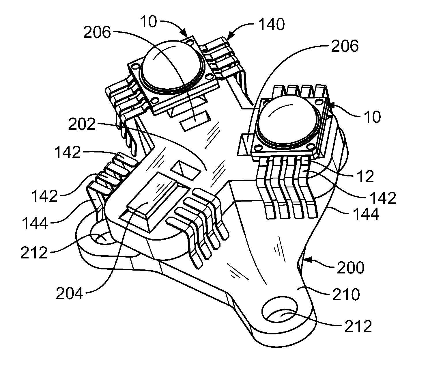
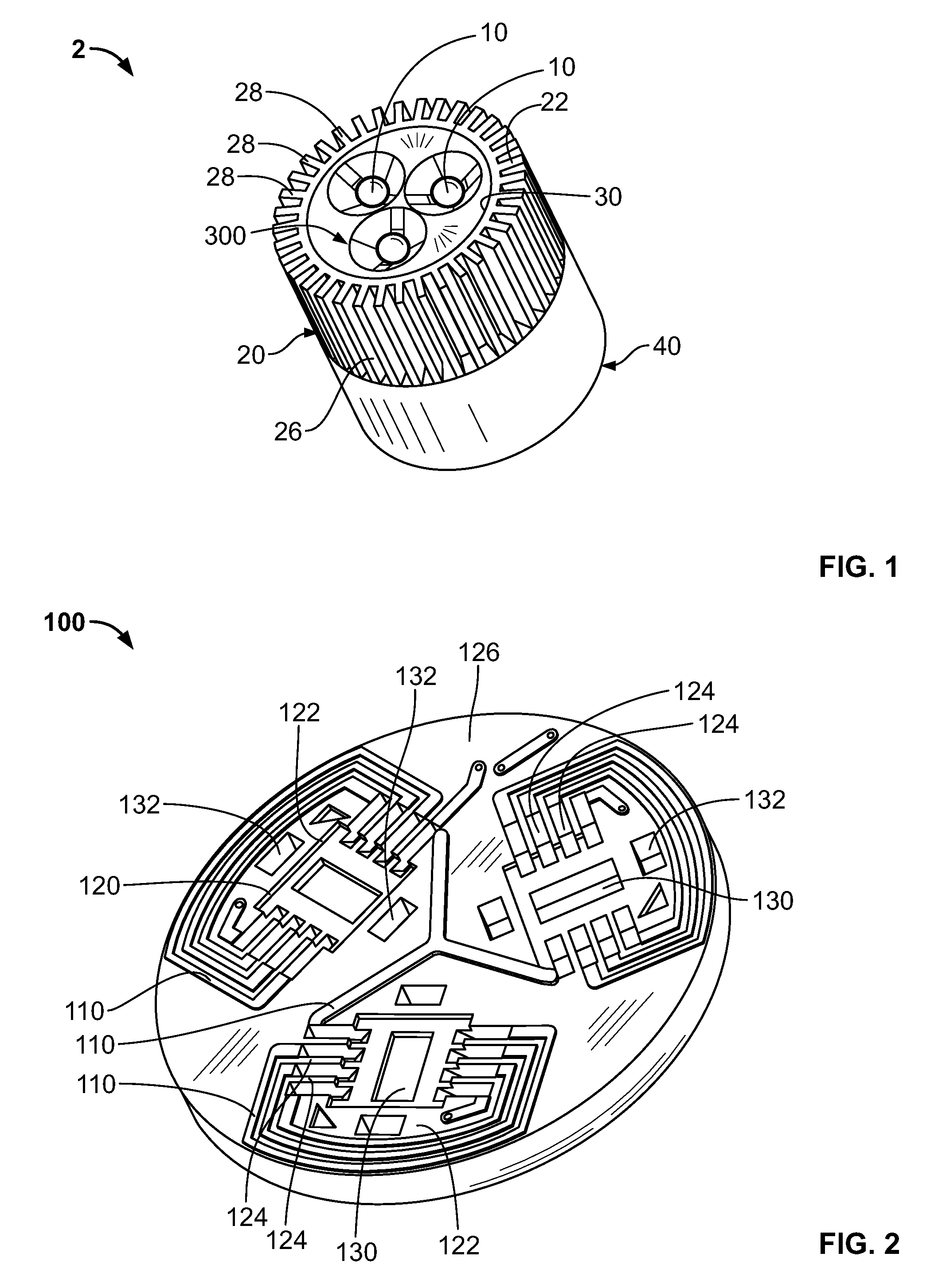
[0036]Referring to FIG. 1, a light-emitting device interconnect assembly 2 is shown. In the embodiment of FIG. 1, three Cree MC-E LEDs (light-emitting diodes) 10 are shown. The luminous flux of the three Cree MC-E LEDs in warm white is roughly equivalent to that of a 50 watt MR 16 halogen bulb or a 60 watt incandescent bulb. However, the invention is not limited to the use of three LEDs or to the particular LEDs shown or to the output described. Any number of light-emitting devices or LEDs 10 can be used without departing from the scope of the invention.

[0037]The assembly 2 has a finned heat sink or top portion 20 and a bottom portion 40. The top portion 20, as shown in FIGS. 1 and 13, has a top surface 22, a bottom surface 24 and a sidewall 26 which extends therebetween. The sidewall 26 has heat transfer fins 28 provided thereon. A component receiving cavity or opening 30 extends from the top surface 22 to the bottom surface 24. The top portion 20 may be made from aluminum, copper,...


PUM


Abstract

A light-emitting device assembly which can be used in many applications has a contact carrier, at least one light-emitting device, a heat sink and at least one securing member. The contact carrier has a light-emitting device receiving region and resilient contacts which are provided proximate to the light-emitting device receiving region. The at least one light-emitting device has leads which extend therefrom to mechanically and electrically engage the resilient contacts. The heat sink is thermally coupled to the at least one light-emitting device. The at least one securing member extends through the contact carrier and into the heat sink to releasably retain the contact carrier and the at least one light-emitting device in position relative to each other and relative to the heat sink.

Description

FIELD OF THE INVENTION[0001]The present invention is directed to an LED connector assembly, and more particularly to an assembly in which the LED is electrically and thermally connected without the use of solder and / or thermal adhesives.BACKGROUND OF THE INVENTION[0002]Illumination assemblies are used in a variety of diverse applications. Traditional illumination assemblies have used lighting sources such as incandescent or fluorescent lights, for example. More recently, other types of light-emitting elements, and light-emitting diodes (LEDs) in particular, have been used in illumination assemblies. LEDs have the advantages of small size, long life, and low power consumption. These advantages of LEDs make them useful in many diverse applications.[0003]For many lighting applications, it is desirable to have one or more LEDs supply the required light intensity and / or distribution. For example, several LEDs can be assembled in an array having small dimensions to provide a high illumina...

Claims


Application Information

Patent Timeline
Patent Type & Authority Applications(United States)
IPC IPC(8): H01L33/00B60Q1/06
CPCF21K9/00F21V29/83H01R13/2442H01R33/7685H05K1/0204H05K1/0284H05K1/183H05K2201/09054H05K2201/09118H05K2201/10106F21V7/0083F21V19/045F21V17/005F21V17/12F21V17/164F21V29/20F21V29/763F21V29/773F21V19/0035F21V19/04F21V29/503F21Y2115/10F21V17/00F21V19/00H01R13/24
Inventor GINGRICH, III, CHARLES RAYMOND
Owner TYCO ELECTRONICS LOGISTICS AG (CH)
Why Eureka
Try Eureka