Car battery system

Active Publication Date: 2010-03-25
SANYO ELECTRIC CO LTD
View PDF11 Cites 108 Cited by
  • Summary
  • Abstract
  • Description
  • Claims
  • Application Information

AI Technical Summary

Benefits of technology

[0010]The battery system described above has the characteristic that line impedances for connection between each battery cell and a battery state detection circuit can be low and uniform allowing extremely high precision measurement of the voltage of each of the many battery cells. This is because the circuit board for a battery state detection circuit in the battery system described above is disposed opposite the terminal plane of a battery block allowing positive and negative electrode terminals of each battery cell to connect to the circuit board over a minimum distance.
[0011]Further, the battery system described above has the characteristic that it can effectively prevent malfunction, smoke, and fire due to an open circuit or short circuit in a wire-harness connecting the many battery cells with a battery state detection circuit, and it can improve reliability and safety by insuring stable, reliable detection of the condition of each battery cell by a battery state detection circuit. This is because the circuit board for a battery state detection circuit is mounted opposite a battery block terminal plane, and the positive and negative electrode terminals of each battery cell are connected to the circuit board. In this configuration, a long wire-harness is not used, and electr

Problems solved by technology
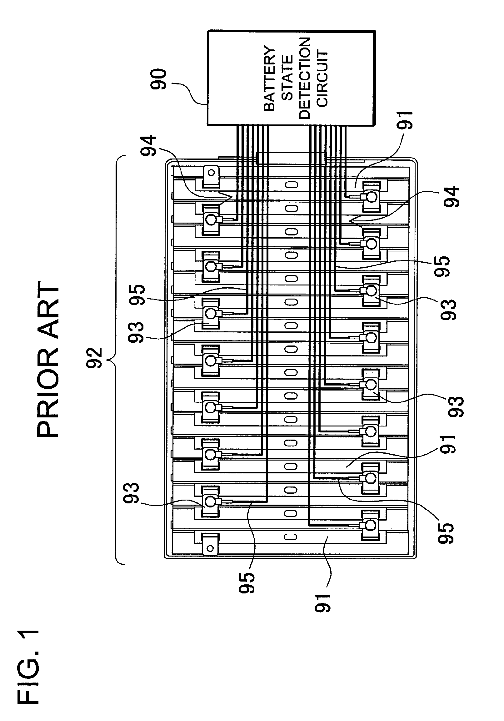
If differences in actual remaining capacity develop, a battery cell with low remaining capacity can easily be over-discharged while a battery cell with high remaining capacity can easily be over-charged, and this can be the cause of battery cell degradation.
This is because a battery cell can be significantly degraded by over-charging or over-discharging.
Since a car battery system is provided with many battery cells, manufacturing cost is extremely high and extending system life-time is of utmost importance.
Differences in wire-lead impedances can be the cause of battery cell v

Method used


Image

  • Car battery system
  • Car battery system
  • Car battery system

Examples


Example

[0031]In the car battery system, the circuit board 57, 67 is provided with an insulating layer 57Y, 67Y on the side facing the battery block 2. This car battery system has the characteristic that battery cell short circuits can be prevented more reliably by the insulating layer provided on the surface of the circuit board facing the battery block.

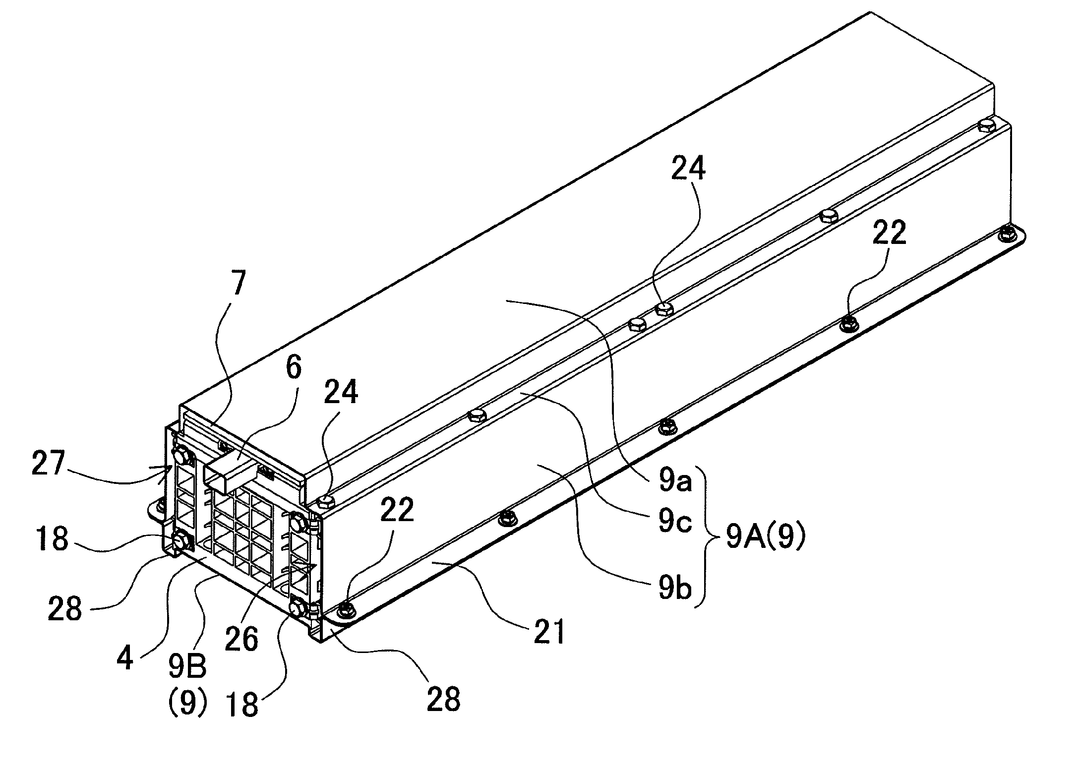
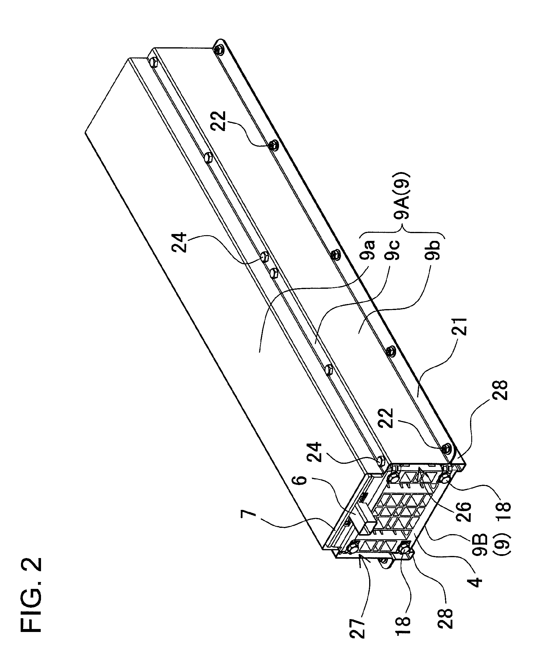
[0032]In the car battery system, temperature sensors 38, which are in thermal contact with the battery cells 1 for battery temperature measurement, can be connected to the circuit board 7, 87. In this car battery system, temperature sensors can be disposed in ideal locations while insuring reliable connection by minimizing the distance between temperature sensors and battery state detection circuits.

[0033]In the car battery system, a liquid filling opening 14 is provided on the terminal surface 1A of each battery cell 1, and the circuit board 7, 87 can have through-holes 7A, 87A opened at positions opposite the battery cell 1 liquid filling...


PUM


Abstract

The car battery system of the present invention is provided with a battery block 2 that retains a plurality of battery cells 1 in a stacked configuration and has a terminal plane 2A, which is coincident with terminal surfaces 1A established by positive and negative battery cell 1 electrode terminals 13; and with a battery state detection circuit 30 that connects with the electrode terminals 13 of each battery cell 1. The battery system is provided with a circuit board 7 with surface-mounted electronic components 40 that implement the battery state detection circuit 30. The circuit board 7 is a single-sided board with electronic components 40 mounted on only one side, and the circuit board 7 is attached to the battery block 2 opposite the terminal plane 2A with the side having no electronic components 40 facing the battery block 2. The positive and negative electrode terminals 13 of each battery cell 1 are connected with the circuit board 7 for connection to the battery state detection circuit 30.

Description

BACKGROUND OF THE INVENTION[0001]1. Field of the Invention[0002]The present invention relates to a car battery system with battery state detection circuits connected to battery blocks having a plurality of battery cells connected in a stacked fashion.[0003]2. Description of the Related Art[0004]A car battery system has many battery cells stacked together and connected in series to increase the output voltage. In this type of battery system, battery cell degradation is prevented by controlling battery charging and discharging while detecting the state of each battery cell. Each battery cell connected in series is charged and discharged by the same current. Remaining battery capacity is computed by integrating battery charging and discharging currents, and charging and discharging is controlled to keep the remaining capacity within a set range. Remaining capacity is computed by adding integrated charging current values and subtracting integrated discharging current values. In practice...

Claims


Application Information

Patent Timeline
IPC IPC(8): G01N27/416H01M50/209H01M50/367H01M50/517H01M50/55H01M50/569
CPCH01M2/1066H01M2/1252H01M2/202H01M2/30H05K1/181H01M10/482H01M10/486H05K1/18H01M10/425Y02E60/10H01M50/209H01M50/367H01M50/517H01M50/55H01M50/569B60L58/10B60L50/50G01R31/3647H01M50/50
Inventor YANO, JYUNYAFURUKAWA, KIMIHIKOTANAKA, KUNIHO
Owner SANYO ELECTRIC CO LTD
Why Eureka
Try Eureka