Differential signal driven direct-current voltage generating device

a voltage generation device and differential signal technology, applied in the direction of electrical apparatus, pulse automatic control, etc., can solve the problem of limited output frequency range, and achieve the effect of widening the output frequency rang

Active Publication Date: 2010-03-25
NAT TAIWAN UNIV
View PDF6 Cites 1 Cited by
  • Summary
  • Abstract
  • Description
  • Claims
  • Application Information

AI Technical Summary

Benefits of technology

[0008]It is therefore an objective of this invention to provide a differential signal driven direct-current voltage generating device that can generate an output of a DC voltage with a wider range that can be used for driving PLL or DLL circuit systems to produce a wider range of output frequencies.

Problems solved by technology

In practice, however, traditional charge pump circuits are only capable of offering a limited output voltage range; and therefore, the VCO circuits are also only capable of offering a limited range of output frequencies in proportion to the charge pump voltages.

Method used


Image

  • Differential signal driven direct-current voltage generating device
  • Differential signal driven direct-current voltage generating device
  • Differential signal driven direct-current voltage generating device

Examples


Embodiment Construction

[0022]The differential signal driven direct-current voltage generating device according to the invention is disclosed in full details by way of preferred embodiments in the following with reference to the accompanying drawings.

Function of the Invention

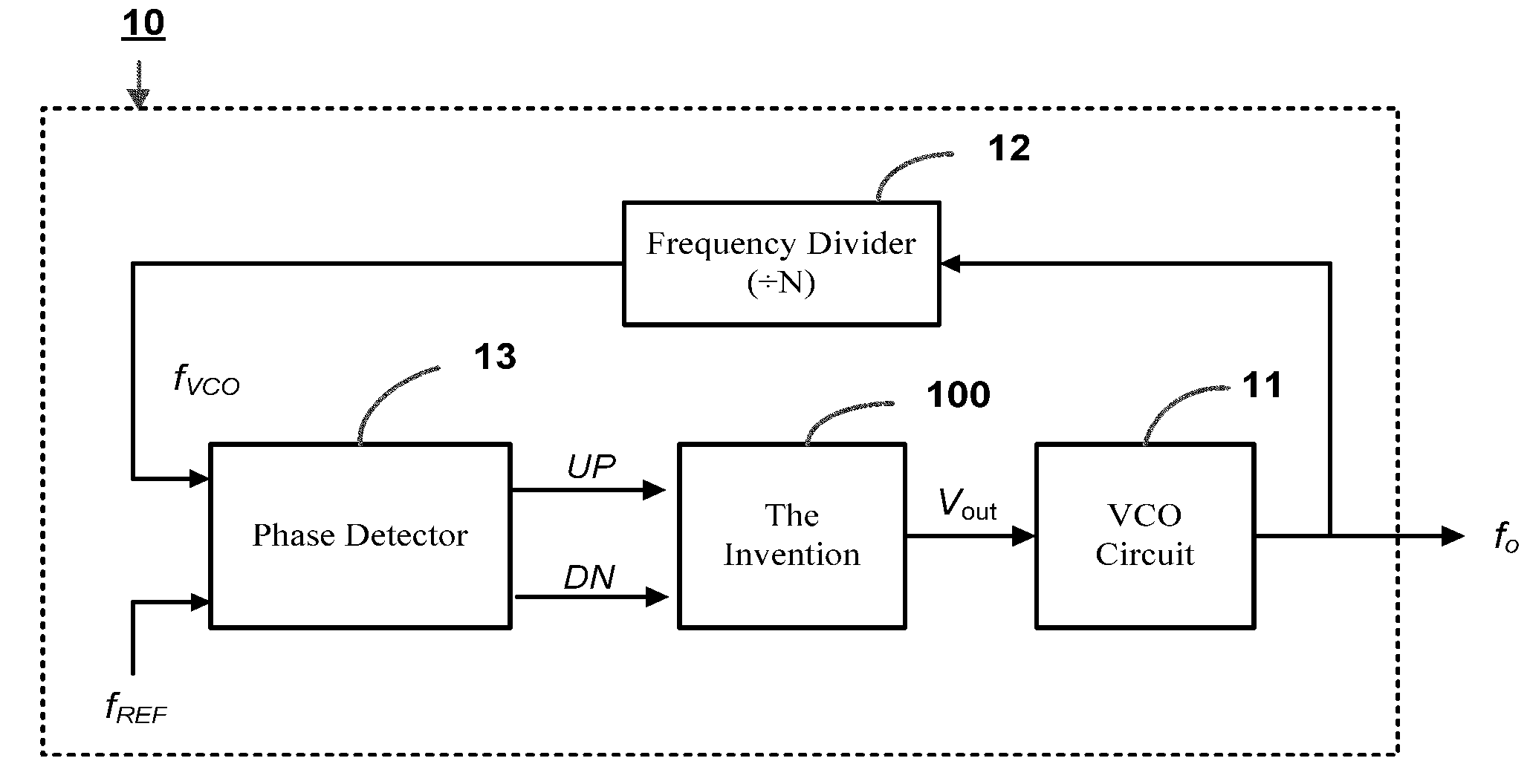
[0023]FIG. 1 is a schematic diagram showing the input / output (I / O) functional model of the differential signal driven direct-current (DC) voltage generating device according to the invention (which is here encapsulated in a box indicated by the reference numeral 100, and is hereinafter referred in short as “DC voltage generating device”). As shown, the DC voltage generating device of the invention 100 is designed with an I / O interface having a pair of input ports (UP, DN) and an output port (Vout), where the input ports (UP, DN) are used for reception of a pair of differential signals, such as a pair of phase-difference signals, which are presented respectively as a pump-up enable signal (UP) and a pump-down enable signal (DN); while t...


PUM


Abstract

A differential signal driven direct-current voltage generating device is proposed, which is designed for use with a PLL (phase-locked loop) circuit or a DLL (delay-locked loop) circuit system for generating an output of a direct-current (DC) voltage in response to a pair of differential signals, such as phase-difference signals; and which is characterized by the utilization of a capacitor-switched voltage doubler for doubling the output voltage of a charge pump so that the doubled voltage can be used as a control voltage for a PLL-VCO (voltage-controlled oscillation) or a DLL-VCDL (voltage-controlled delay line) circuit for generation of an output oscillating signal with a wider frequency range.

Description

BACKGROUND OF THE INVENTION[0001]1. Field of the Invention[0002]This invention relates to electronic circuit technology, and more particularly, to a differential signal driven direct-current (DC) voltage generating device which is designed for integration to a PLL (phase-locked loop) or a DLL (delay-locked loop) circuit system for generating an output of a DC voltage in response to an input of a differential signal, such as a phase-difference signal.[0003]2. Description of Related Art[0004]In PLL (phase-locked loop) and DLL (delay-locked loop) circuitry, the charge pump is an essential circuit component capable of being driven by a pair of phase-difference signals (which respectively indicate the lagging or leading of the output frequency generated by the PLL or DLL circuitry with respect to a reference frequency) and responsively generating an output of a DC voltage whose amplitude is proportional to the phase difference between the output frequency and the reference frequency. Fun...

Claims


Application Information

Patent Timeline
Patent Type & Authority Applications(United States)
IPC IPC(8): H03L7/06
CPCH03L7/0891H03L7/18H03L7/093
Inventor HOPPNER, SEBASTIANTSAI, ZUO-MINWANG, HUEI
Owner NAT TAIWAN UNIV
Why Eureka
Try Eureka