A Feedback Regulated Oscillator

A technology of feedback adjustment and oscillator, applied in the direction of automatic power control, electrical components, etc., can solve the problems of lower circuit accuracy, poor accuracy, and inability to take into account, so as to broaden the output frequency range, improve the accuracy of the oscillator, and improve the accuracy Effect

Active Publication Date: 2022-01-14
BEIJING SMARTCHIP MICROELECTRONICS TECH COMPANY +3
View PDF4 Cites 0 Cited by
  • Summary
  • Abstract
  • Description
  • Claims
  • Application Information

AI Technical Summary

Problems solved by technology

[0003] On the one hand, with the development of integrated circuits, electronic systems have higher and higher requirements for low voltage, low power consumption, and high precision characteristics of oscillator circuits, and existing oscillators either cannot take into account various characteristics, or require Adding large-scale peripheral circuits, or the details are not handled well, and problems such as frequency deviation introduced due to current source imbalance and limited loop adjustment ability cannot be solved, so it cannot fully meet the OSC circuit design requirements
[0004] In the second aspect, because the period of the OSC circuit is related to the delay, and the delay time is greatly affected by the process, temperature, bias signal, etc., this will greatly reduce the accuracy of the circuit, and as the output frequency increases, the accuracy will become worse
[0005] Therefore, today's OSC circuit structure cannot meet the characteristic requirements of low voltage, low power consumption and / or high precision

Method used


Image

  • A Feedback Regulated Oscillator
  • A Feedback Regulated Oscillator
  • A Feedback Regulated Oscillator

Examples


Embodiment Construction

[0031] The specific implementation manners of the embodiments of the present invention will be described in detail below in conjunction with the accompanying drawings. It should be understood that the specific implementation manners described here are only used to illustrate and explain the embodiments of the present invention, and are not intended to limit the embodiments of the present invention.

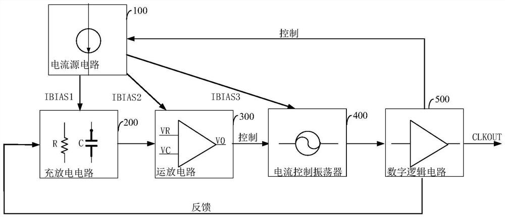
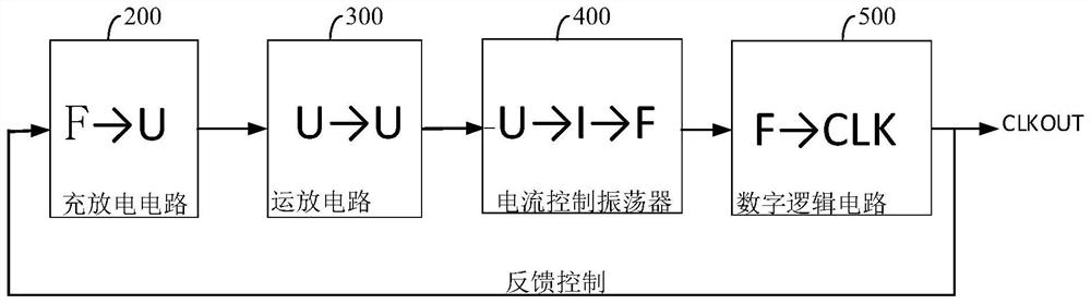
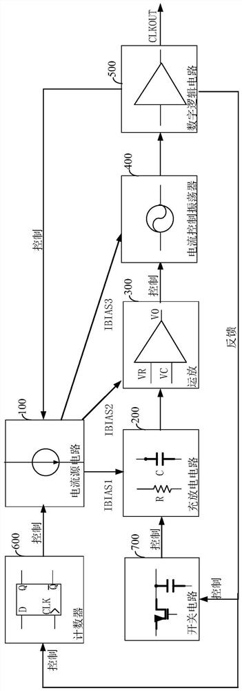
[0032] figure 1 is a structural schematic diagram of a feedback-regulated oscillator according to an embodiment of the present invention. It should be noted that the abbreviation "oscillator" mentioned below refers to the feedback-regulated oscillator here, and it can also represent the entire circuit about the oscillator, while for the current-controlled oscillator, voltage-controlled oscillator and Related subcircuits will be described with their full names.

[0033] Such as figure 1 As shown, the feedback regulated oscillator may include the following parts:

[0034] 1) The...


PUM


Abstract

The invention provides a feedback regulating oscillator, which belongs to the technical field of integrated circuits. The oscillator includes: a current source circuit for outputting three bias currents; a charging and discharging circuit for charging and discharging according to the first bias current, converting a correspondingly generated frequency signal into a voltage signal and output; an operational amplifier circuit, configured to start working in response to the second bias current, to amplify and output the voltage signal; a current-controlled oscillator, configured to amplify the voltage signal according to the third bias current, The amplified voltage signal is converted into a current signal, and then the current signal is converted into a clock signal in the form of frequency and output; and a digital logic circuit is used to convert the clock signal into a clock control signal and output and control the clock The signal is fed back to the charging and discharging circuit and the current source circuit. The present invention can meet the requirements of any one or more of low voltage, low power consumption, and high precision characteristics.

Description

technical field [0001] The invention relates to the technical field of integrated circuits, in particular to a feedback regulation oscillator. Background technique [0002] Oscillators (OSCs) are an integral part of many electronic systems and are widely used in communications and various electronic devices, ranging from clock generation in microprocessors to carrier synthesis in cellular phones. However, the inventor of the present application found that the existing OSC circuit also has the following two problems in the process of realizing the present invention: [0003] On the one hand, with the development of integrated circuits, electronic systems have higher and higher requirements for low voltage, low power consumption, and high precision characteristics of oscillator circuits, and existing oscillators either cannot take into account various characteristics, or require Adding large-scale peripheral circuits, or the details are not handled well, and problems such as ...

Claims


Application Information

Patent Timeline
Patent Type & Authority Patents(China)
IPC IPC(8): H03L7/099
CPCH03L7/099
Inventor 胡毅唐晓柯肖衍马永旺甘杰李振国金鑫张帆
Owner BEIJING SMARTCHIP MICROELECTRONICS TECH COMPANY
Why Eureka
Try Eureka