Method and apparatus for radar surveillance and detection of sea targets

a radar and target detection technology, applied in the field of sea target detection, can solve the problems of unable to detect hovering craft, most sea targets, and small cells, and achieve the effect of preventing biasing the detection

Inactive Publication Date: 2010-03-25
LOCKHEED MARTIN CORP
View PDF36 Cites 97 Cited by
  • Summary
  • Abstract
  • Description
  • Claims
  • Application Information

AI Technical Summary

Benefits of technology

[0006]This invention further includes an apparatus having: (1) a processor for: (a) creating a map of measurements of a surrounding environment of the cell under test; (b) sorting selected measurements of a surrounding environment of the cell under test; (c) removing any selected measurement of the surrounding environment if the magnitude of the selected measurement is larger than a pre assigned value to preven

Problems solved by technology

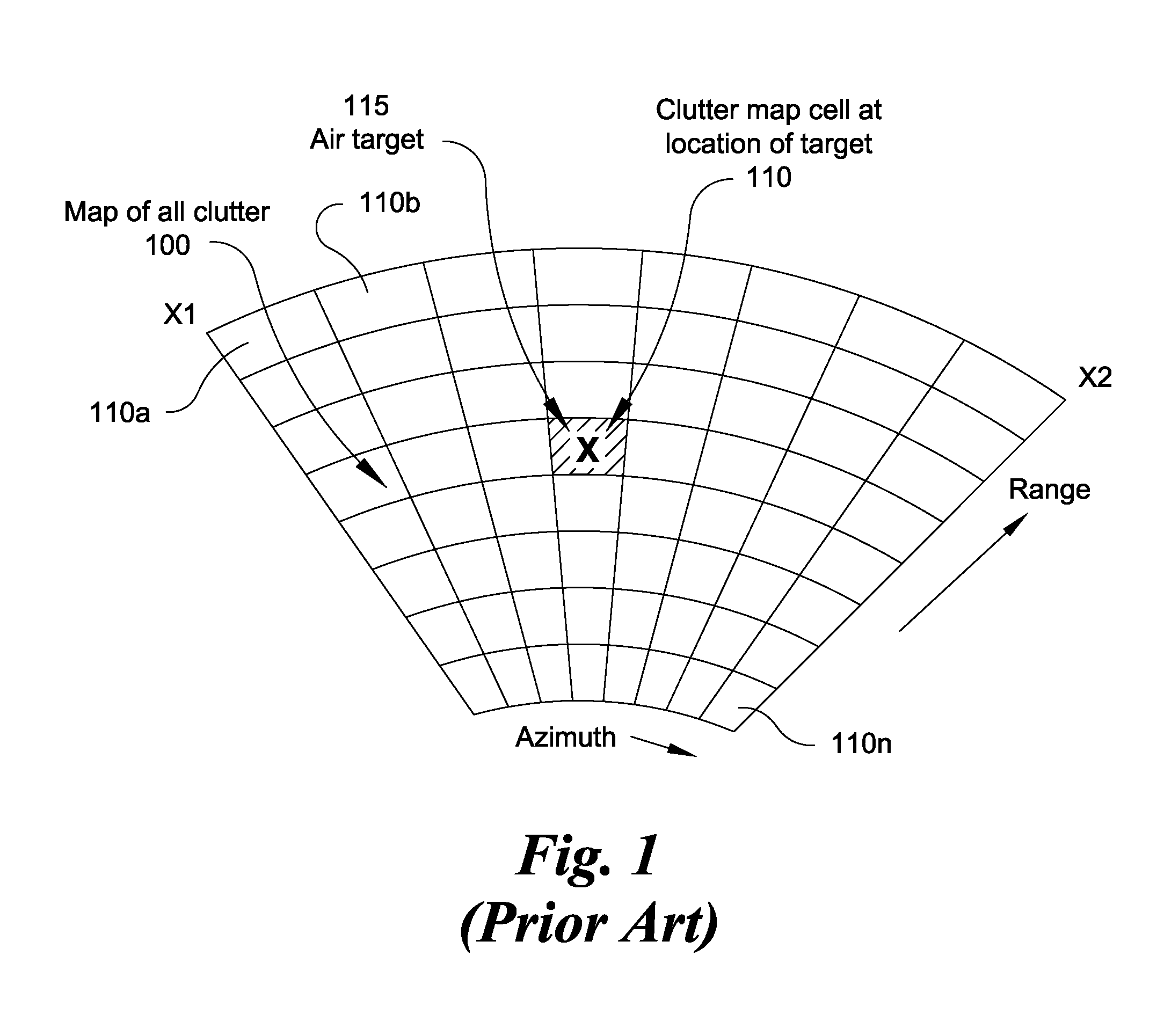
However, defining cells sufficiently small, to allow air targets to have velocity sufficiently high, fails for detection of hovering craft, such as helicopters, and most sea targets where the target velocity is relatively low or virtually zero.
This is known as “mapping out.” Efforts to detect a hovering

Method used


Image

  • Method and apparatus  for radar surveillance and detection of sea targets
  • Method and apparatus  for radar surveillance and detection of sea targets
  • Method and apparatus  for radar surveillance and detection of sea targets

Examples


Embodiment Construction

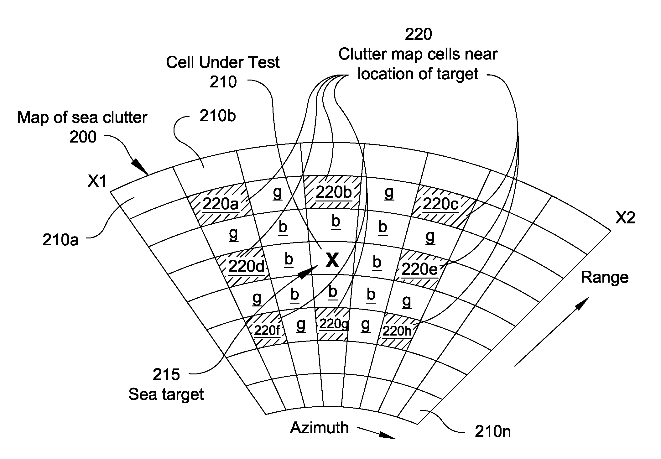
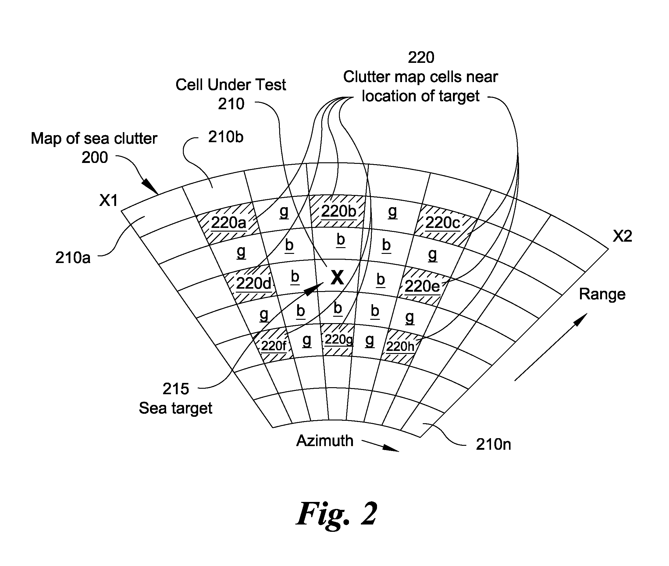
[0015]The following description of the preferred embodiments is merely by way of example and is not intended to limit the invention or its application. The subject invention allows a conventional air target surveillance radar using prior art map based CFAR detection system to further detect slow or stationary targets on or hovering above a homogeneous surface such as a body of water. While preferred embodiments of the present invention are described with respect to slow or stationary targets on or hovering above the sea surface (sea targets), the present invention contemplates that sea targets further include those slow moving, non-moving and hovering targets on or above other homogeneous surfaces such as homogeneous desert sands, frozen Antarctic terrain or frozen water, and the like. Furthermore, while slow moving targets as described herein are typically surface craft, buoys, hovering helicopters, growler icebergs, periscopes and the like, it is further contemplated that targets ...


PUM


Abstract

In a radar system that detects relatively fast moving targets using a radar clutter map comprising a plurality of range-azimuth cells containing parameter data values indicative of time averaged echo returns for affecting alarm threshold levels at range-azimuth locations scanned by the radar system antenna, a method for detecting relatively slow moving targets in a substantially homogeneous surveillance region, the method comprising the steps of obtaining from the radar clutter map a value corresponding to parameter data of a given cell under test (CUT); determining a second parameter data value using parameter data values of other cells from the plurality of range-azimuth cells from the radar clutter map; comparing the parameter data value of the CUT with the second parameter data value; and generating a signal indicative of a target detection when the CUT parameter data value exceeds the second parameter data value by a given threshold corresponding to a target false alarm rate.

Description

FIELD OF INVENTION[0001]The present invention relates to sea target detection with an air target surveillance radar using map based constant false alarm rate processing.BACKGROUND OF THE INVENTION[0002]Radar systems used for surveillance and tracking generally require some type of target processing for background estimation, detection threshold and constant false alarm control. In air target radars, this has typically been achieved with range-only constant false alarm rate (“CFAR”) processing or range and velocity CFAR processing or “area CFAR.”[0003]Contemporary radars frequently accomplish the CFAR function with clutter maps containing running averages of received power for every multidimensional resolution cell, i.e. every range-azimuth-Doppler cell. The clutter map is then used to establish detection thresholds whereby new data is compared to the running average in each cell. In effect the compare process identifies target returns that have magnitudes above specified values when...

Claims


Application Information

Patent Timeline
IPC IPC(8): G01S13/42G01S13/52
CPCG01S13/5248G01S7/2923
Inventor STOCKMANN, PETER H.
Owner LOCKHEED MARTIN CORP
Why Eureka
Try Eureka