Method For Precisely Measuring Position Of A Part To Be Inspected At A Part Inspection Station

a technology for precisely measuring the position of parts to be inspected at a part inspection station, which is applied in the direction of optical radiation measurement, distance measurement, instruments, etc., can solve the problems of inability to successfully measure the inspection region, inability to accurately measure the lead deviation in the current implementation, and bias in the measurement of threads

Active Publication Date: 2010-03-25
GII ACQUISITION LLC DBA GENERAL INSPECTION
View PDF40 Cites 21 Cited by
  • Summary
  • Abstract
  • Description
  • Claims
  • Application Information

AI Technical Summary

Benefits of technology

[0053]Further in carrying out the above object and other objects of the present invention, a method for precisely measuring position of a part to be inspected at a part inspection station is provided. The method includes positioning a part having a part axis relative to a measurement axis at the part inspection station and scanning the positioned part with an array of planes of radiation so that the part occludes each of the planes of radiation over a measurement interval of the part to create a corresponding array of unobstructed planar portions of the planes of radiation. Each of the unobstructed planar portions contains an amount of radiation which is representative of a respective geometric dimension of the part. The method further includes measuring the amount of radiation present in each of the unobstructed planar portions to obtain measurement signals and processing the measurement signals to obtain a measure of distance between the axes at the measurement interval.
[0054]Still further in carrying out the above object and other objects of the present invention, a method for precisely measuring position of a part to be inspected at a part inspection station is provided. The method includes positioning a part having a part axis relative to a measurement axis at the part inspection station and scanning the positioned part with an array of planes of radiation so that the part occludes each of the planes of radiation over a measurement interval of the part to create a corresponding array of unobstructed planar portions of the planes of radiation. Each of the unobstructed planar portions contains an amount of radiation which is representative of a respective geometric dimension of the part. The method further includes measuring the amount of radiation present in each of the unobstructed planar portions to obtain measurement signals and processing the measurement signals to obtain a measure of angle between the axes at the measurement interval.

Problems solved by technology

Incorrect fit to a non cylindrical cross section would lead to incorrect lead deviation measures in the current implementation.
Failure to meet the requirements will typically lead to bias in the thread measurement, or in a failure to successfully measure the inspection region.

Method used


Image

  • Method For Precisely Measuring Position Of A Part To Be Inspected At A Part Inspection Station
  • Method For Precisely Measuring Position Of A Part To Be Inspected At A Part Inspection Station
  • Method For Precisely Measuring Position Of A Part To Be Inspected At A Part Inspection Station

Examples


Embodiment Construction

[0117]The overall system described in this application is referred to as “Laser Lab.” Laser Lab is a trademark of the assignee of this application. It is to be understood that numerous inventions are described in this application, of which only some are claimed. The other disclosed inventions are claimed in the applications noted in the Cross Reference to Related Applications part of this application. It is also to be understood that a number of words and phrases are explained in a Glossary portion of this application. The Glossary explains but does not unduly limit the words and phrases contained in this application.

Laser Lab—Physical Overview

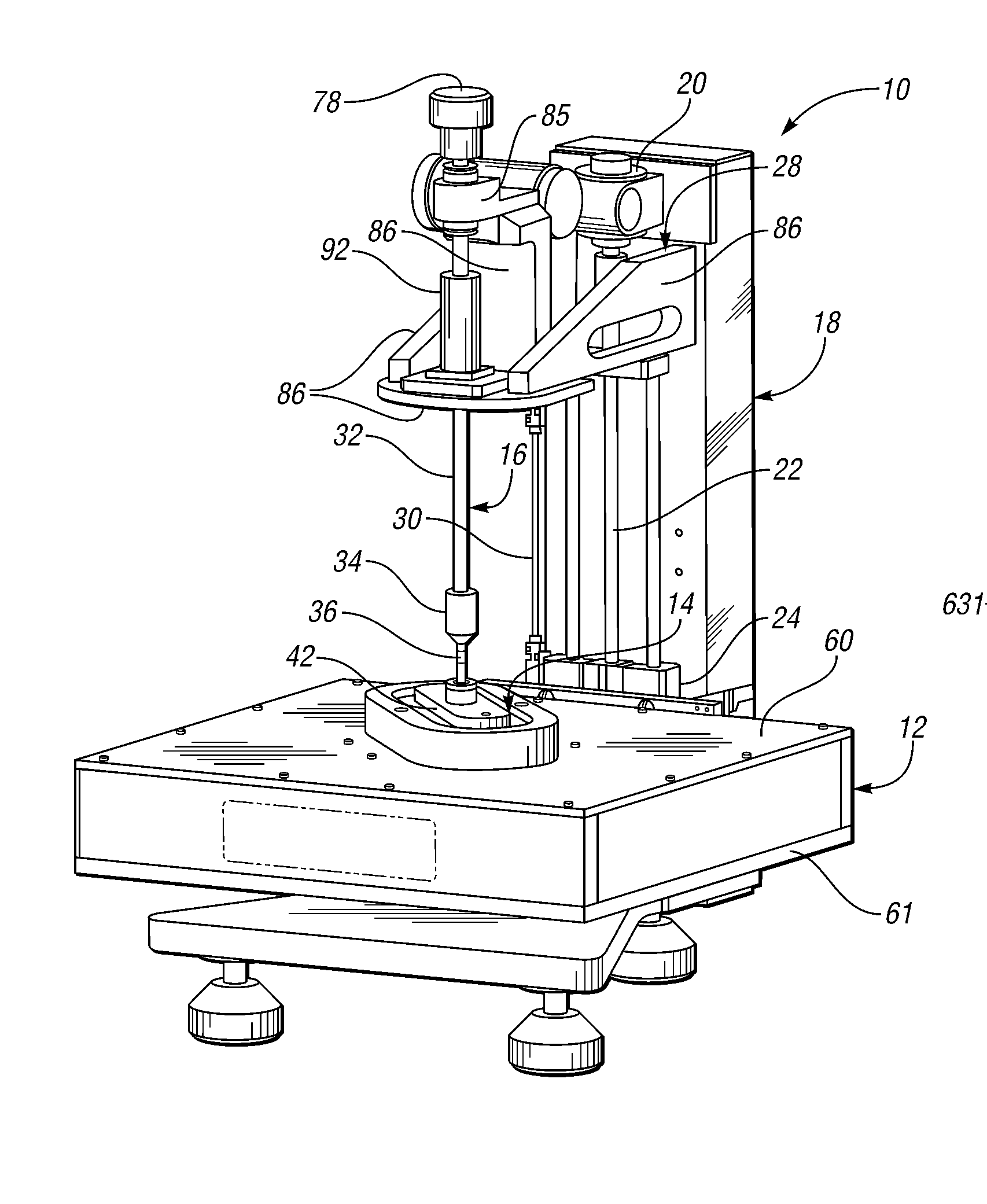
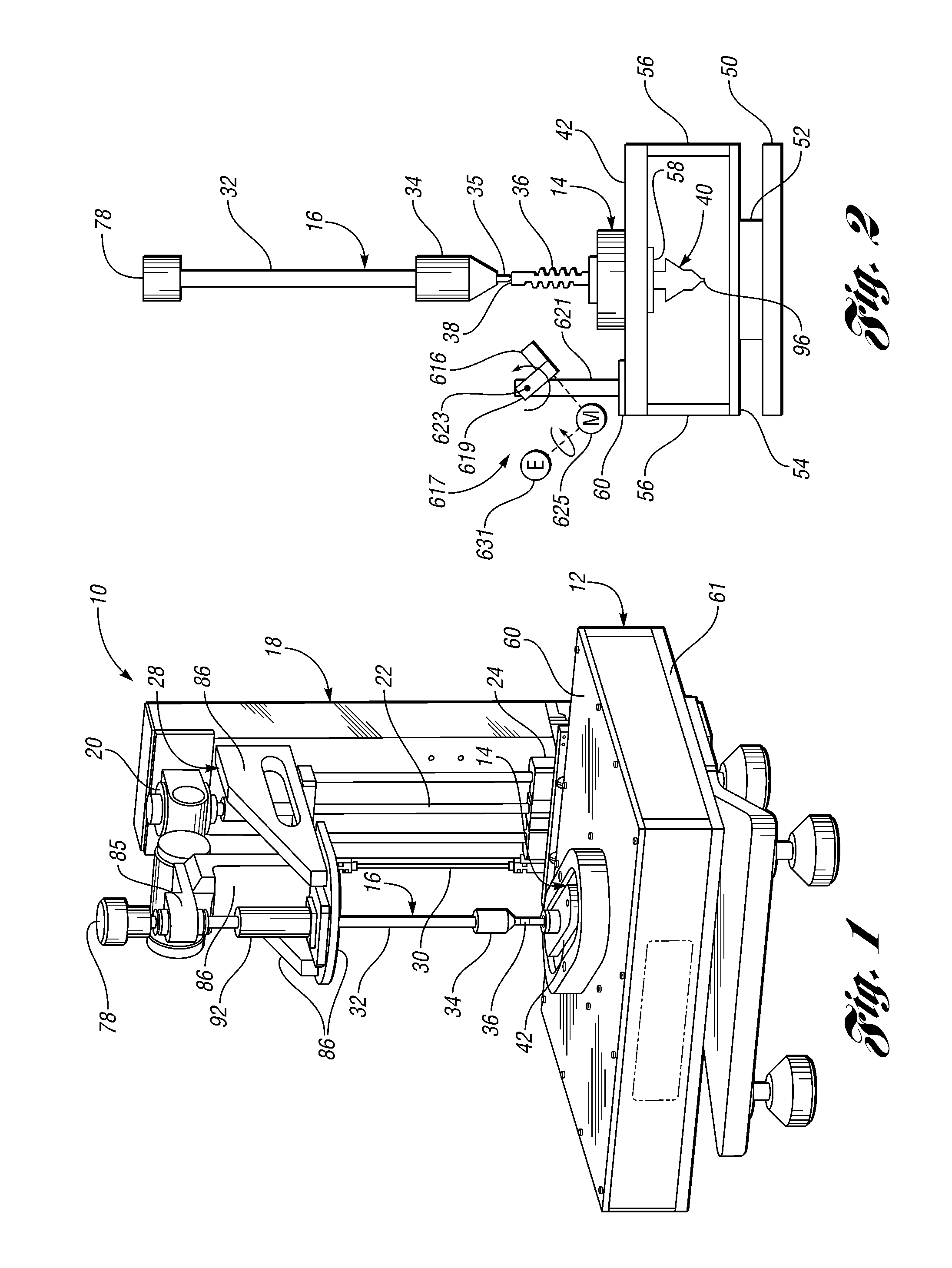
[0118]The Laser Lab system (i.e., FIG. 1) includes several physical subsystems or units.

[0119]A PC tower unit (i.e., FIG. 8) contains a computer and a number of additional control electronics modules. It has a rear panel with connectors for light curtain / safety electronics, motor control, linear encoder, measurement signals, and optical head c...


PUM


Abstract

A method for precisely measuring position of a part to be inspected at a part inspection station is provided. The method includes positioning a part having a part axis relative to a measurement axis at the part inspection station and scanning the positioned part with an array of planes of radiation so that the part occludes each of the planes of radiation over a measurement interval of the part to create a corresponding array of unobstructed planar portions of the planes of radiation. Each of the unobstructed planar portions contains an amount of radiation which is representative of a respective geometric dimension of the part. The method also includes measuring the amount of radiation present in each of the unobstructed planar portions to obtain measurement signals and processing the measurement signals to obtain a geometric measurement between the axes at the measurement interval. The geometric measurement may be a distance between the axes or angle between the axes. If the geometric measurement is outside an acceptable range of geometric values, the method may further include repositioning the part until the geometric measurement between the axes at the measurement interval is within the acceptable range of geometric values.

Description

CROSS-REFERENCE TO RELATED APPLICATIONS[0001]This application is related to the following commonly-owned U.S. patent applications which are filed on the same day as this application:[0002]1) Non-contact Method and System for Inspecting Parts (Attorney Docket No. GINS 0137 PUS); and[0003]2) Method and System for Inspecting Parts Utilizing Triangulation (Attorney Docket No. GINS 0138 PUS).[0004]This application is related to the following commonly-owned U.S. patent applications which were filed on Oct. 23, 2007:[0005]1) Method and System for Optically Inspecting Parts (U.S. Ser. No. 11 / 977,117);[0006]2) Method for Estimating Thread Parameters of a Part (U.S. Ser. No. 11 / 977,097);[0007]3) Optical Modules and Method of Precisely Assembling Same (U.S. Ser. No. 11 / 977,102);[0008]4) Method and Inspection Head Apparatus for Optically Measuring Geometric Dimensions of a Part (U.S. Ser. No. 11 / 977,010);[0009]5) Apparatus for Quickly Retaining and Releasing Parts to be Optically Measured (U.S....

Claims


Application Information

Patent Timeline
Patent Type & Authority Applications(United States)
IPC IPC(8): G01B11/14
CPCG01B11/2425G01B11/245G01B11/2433
Inventor SPALDING, JOHN D.WALSTRA, ERIC M.
Owner GII ACQUISITION LLC DBA GENERAL INSPECTION
Why Eureka
Try Eureka