Image encoder, image decoder, and image encoding system

Active Publication Date: 2010-03-25
OKI ELECTRIC IND CO LTD
View PDF11 Cites 7 Cited by
  • Summary
  • Abstract
  • Description
  • Claims
  • Application Information

AI Technical Summary

Benefits of technology

[0014]The invention also provides an image coding system including the above image encoder and image decoder. This system can be used with Slepian-Wolf coding employing either a turbo code or an LDPC code. By using a less computationally intensive process to predict parts of the image that are easy to predict because they are not significantly changed, the invented system reduces the computational load on the image decoder, without loss of prediction accuracy.
[0015]In a closely related embodi

Problems solved by technology

DVC systems in general place a high computational load on the decoder.
This is partly because the decoding of turbo codes and LCPC codes is computationally intensive, but another factor is that the generation of predicted images is computationally intensive because of the need to carry out motion compensat

Method used


Image

  • Image encoder, image decoder, and image encoding system
  • Image encoder, image decoder, and image encoding system
  • Image encoder, image decoder, and image encoding system

Examples


Example

First Embodiment

[0028]When a simple prediction process is used in distributed video coding, if part of an image to be encoded differs greatly from the reference image from which the image will be predicted in the decoder, the result is a burst of prediction errors in that part of the image. Since the effect on the decoding process is similar to the effect of a burst error in a communication channel, a part of the image that is significantly changed with respect to the reference image can be considered to have a type of ‘burst error’. This terminology does not imply that the image data are in error; it only means that the image data are hard to predict. The first embodiment detects such burst errors in the encoder, and compensates for them by putting extra computational effort into the prediction process in the decoder.

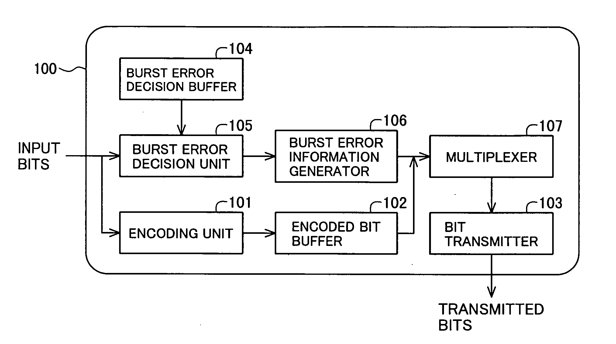
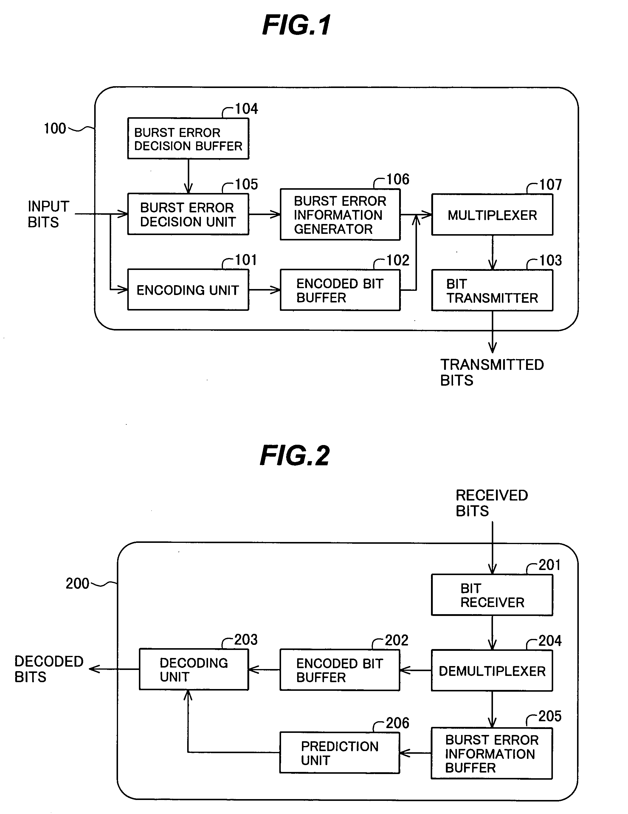
[0029]Referring to FIG. 1, the image encoder 100 in the first embodiment comprises an encoding unit 101, an encoded bit buffer 102, an output unit or bit transmitter 1...

Example

Second Embodiment

[0063]Whereas motion compensation was used as an exemplary method of generating the predicted image data in the first embodiment, the second embodiment uses a simpler prediction method. For example, a preceding frame may be used without alteration as the predicted image, or the values in preceding and following frames may be arithmetically averaged to produce the predicted image.

[0064]Referring to FIG. 4, the image encoder 100 in the second embodiment includes a burst error decision unit 108 that differs from the burst error decision unit 105 in the first embodiment. The method by which the burst error information generator 108 identifies significantly changed parts of the input image will be described below.

[0065]Referring to FIG. 5, the image decoder 200 in the second embodiment includes a prediction unit 207 that differs from the prediction unit 206 in the first embodiment, and also includes a prediction revision unit 208.

[0066]The burst error information buffer ...

Example

Third Embodiment

[0084]The third embodiment is identical to the first embodiment with the added condition that a Slepian-Wolf coding method is used. That is, the burst error detection and prediction processing features of the first embodiment are added to a conventional Slepian-Wolf coding system. Since the third embodiment can be understood from the description of the first embodiment and a knowledge of conventional Slepian-Wolf coding, the description of the third embodiment will focus on a description of the conventional DVC coding system described by Aaron et al. in the reference cited above.

[0085]Referring to FIG. 7, in this conventional DVC coding system, some frames, referred to as key frames, are encoded and decoded by intraframe processing, while other frames, referred to as Wyner-Ziv frames, are encoded by intraframe processing and decoded by interframe processing. In the encoding process, a discrete cosine transform (DCT) is used to transform each Wyner-Ziv frame to the co...


PUM


Abstract

An image coding system includes an image encoder and a predictive image decoder. The image encoder encodes an input image to obtain encoded data, compares the input image with a reference image, generates error information identifying parts of the input image that are changed with respect to the reference image, and outputs the encoded data and the error information. The predictive image decoder predicts the image, using a simplified prediction method for parts of the image identified by the error information as not being changed, and decodes the encoded data and the predicted data to obtain decoded image data. Use of the simplified prediction method in unchanged parts of the image reduces the prediction processing load without significant loss of prediction accuracy.

Description

BACKGROUND OF THE INVENTION[0001]1. Field of the Invention[0002]The present invention relates to an image coding system, such as a distributed video coding system, having an image encoder and a predictive image decoder.[0003]2. Description of the Related Art[0004]Distributed video coding (DVC) has been attracting considerable attention recently. In a DVC system, Slepian-Wolf techniques are used to decode an encoded image with reference to a predicted image generated by the decoder. In ‘Transform-Domain Wyner-Ziv Codec for Video’, Proc. SPIE Visual Communications and Image Processing, San Jose, Calif., 2004, Aaron et al. describe a DVC system in which the underlying code is a turbo code. Turbo codes are explained by Sklar in Digital Communications: Fundamentals and Applications, 2nd edition, Prentice-Hall, 2001. Low-density parity-check (LDPC) codes can be used in place of turbo codes.[0005]DVC systems in general place a high computational load on the decoder. This is partly because ...

Claims


Application Information

Patent Timeline
IPC IPC(8): H04N7/32G06K9/36H04N7/26H04N19/50H03M13/09H03M13/19H03M13/29H04N19/102H04N19/103H04N19/105H04N19/114H04N19/136H04N19/157H04N19/196H04N19/46H04N19/503H04N19/51H04N19/573H04N19/61H04N19/625H04N19/65H04N19/67H04N19/70H04N19/89H04N19/93
CPCH04N19/105H04N19/507H04N19/166H04N19/61
Inventor NISHI, TAKASHI
Owner OKI ELECTRIC IND CO LTD
Why Eureka
Try Eureka