Curvilinear spinal access method and device

a curvilinear and spine technology, applied in the field of surgery, can solve the problems of inability to safely allow revision or re-exploration, limited widespread adoption of techniques in the medical community, and increased complication

Inactive Publication Date: 2010-03-25
ALPHATEC SPINE INC
View PDF5 Cites 169 Cited by
  • Summary
  • Abstract
  • Description
  • Claims
  • Application Information

AI Technical Summary

Benefits of technology

[0011]In a first aspect, embodiments of the present invention provide a curvilinear access device having an expandable working portal. The device includes a slide having an channel with an open top and a movable top sized to cover the open top of the channel forming an expandable working portal with a proximal end and a distal end, wherein the movable top is movable between a closed position and an open position, wherein in the closed position the movable top blocks direct visualization between the proximal end and the distal end of the expandable working portal, and in the open position movement of the movable top results in direct visualization from the proximal end to the distal end of the expandable working portal.
[0039]In another aspect, embodiments of the present invention provide a method for performing a surgical procedure on the spine of a patient. The method includes advancing a distal end of a curvilinear access device at a surgical site located at the spine of the patient, the curvilinear access device including a slide having a channel with an open top and a movable top sized to cover the open top of the channel forming an expandable working portal with a proximal end and a distal end, wherein the movable top is movable between a closed position and an open position, wherein in the closed position the movable top blocks direct visualization between the proximal end and the distal end of the expandable working portal and in the open position movement of the movable top results in direct visualization from the proximal end to the distal end of the expandable working portal, moving the movable top from the closed to the open position, directly viewing the surgical site through working portal and advancing at least one surgical tool and / or at least one implant toward the surgical site via the working portal to perform the surgical procedure.
[0055]In many embodiments, the sequential dilators can be implemented with an impacting wand configured to aid in impacting an initial dilator in the plurality of sequential dilators into annulus.

Problems solved by technology

While these procedures are an improvement over conventional surgery in that muscular disruption and trauma are minimized, difficulties in the techniques have limited widespread adoption in the medical community.
Anterior approaches also do not safely allow for revision or re-exploration and can incur additional complication such as ileus and abdominal pain.
Should further fixation be required these approaches do not allow posterior fixation without repositioning the patient; this procedure is commonly called a 360 operation where the operation begins with the patient in the supine position for the ALIF procedure and then flipped, re-sterilized and posterior fixation is applied with the patient in the prone position.
These procedures increase time of operations which directly relates to blood loss, recovery time and hospital fees.
Posterior and transverse approaches require provide some advantages over anterior approaches yet still require some exposure of the nerves or theral sac, making placement of large (and therefore more stable) implants difficult; therefore posterior and transverse approaches use fixation devices smaller than anterior approaches.
Extreme lateral approaches still provide some advantages over previously discussed procedures yet require cumbersome positioning, long operating distances and provide no access to the spinal canal.
In these approaches the patient is placed on their side which allows a larger access area to implant a bigger device but does not overcome the setback of repositioning the patient should posterior fixation be required.

Method used


Image

  • Curvilinear spinal access method and device
  • Curvilinear spinal access method and device
  • Curvilinear spinal access method and device

Examples


example procedure

A

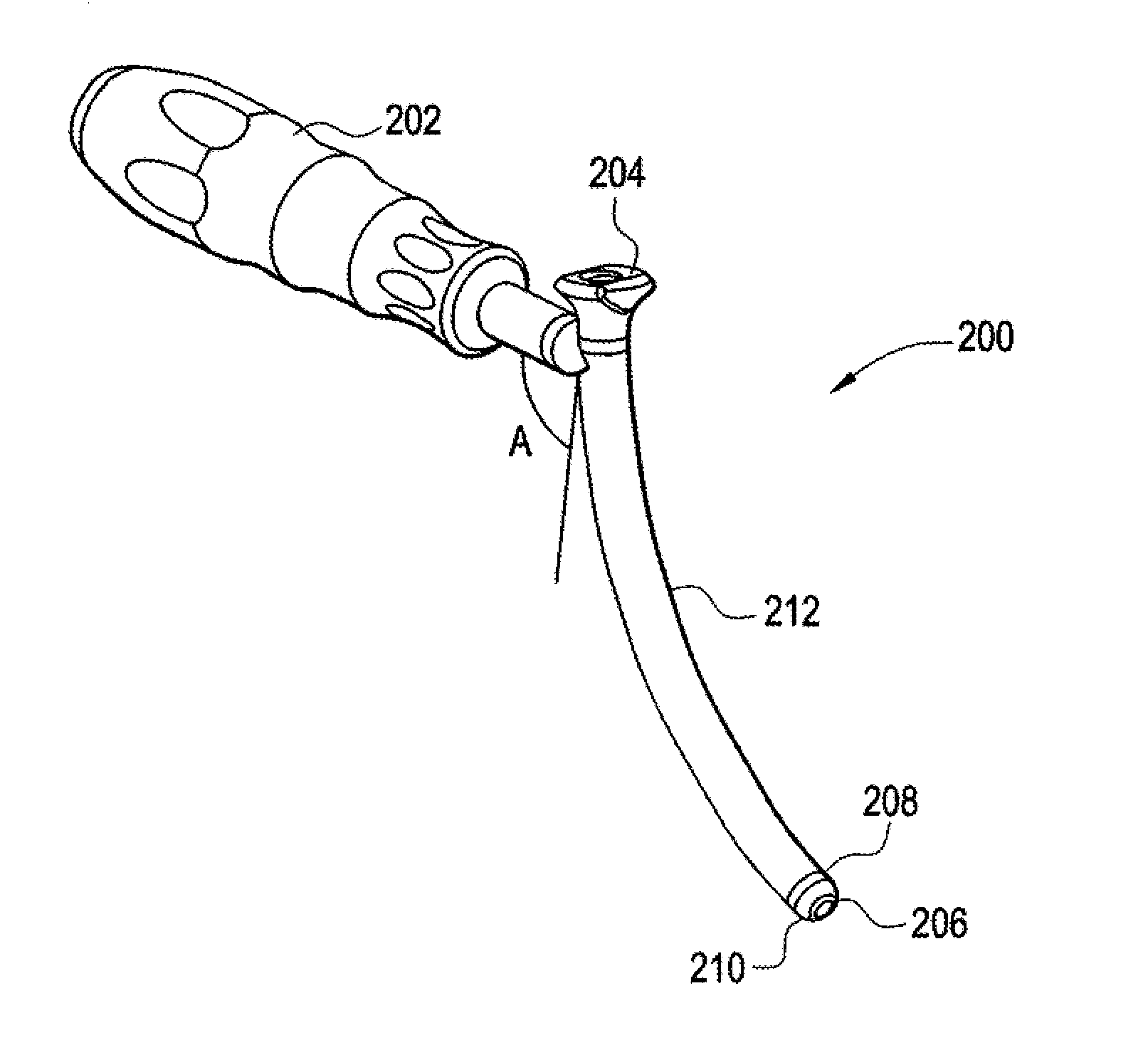
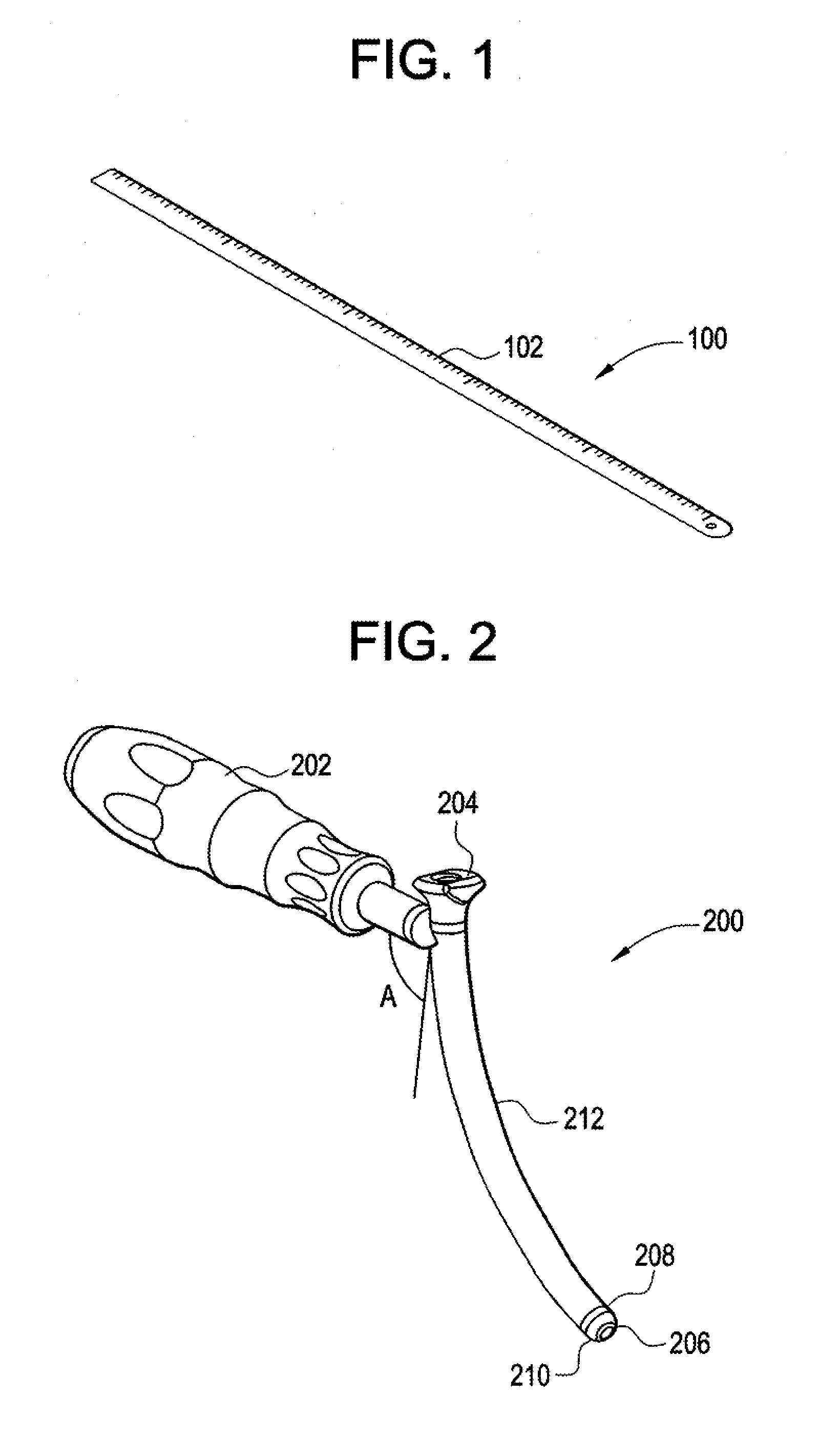
[0164]This example procedure is generally related to many of the embodiments disclosed in FIGS. 1-44c.

[0165]The procedure begins with placing the patient in a prone position and arranging the proper drapery to establish proper sterilization of the operation site. Next, the surgeon uses a measuring device to measure a specified distance from the midline. At this point, the surgeon will make a mark using some marking device as a reference point to create an incision. The specified distance can be calculated using a chart or sliding scale that determines the appropriate distance to make the incision. This distance is directly related to the distance of the center of the vertebral body to the flat surface of the patient's back; given this distance along with the known arc angle of the portal and known center of the midline, the incision distance can be properly calculated.

[0166]An incision is created at the marked point and the surgeon performs blunt dissection with a finger to estima...

example procedure b

[0175]This example procedure is generally related to many of the embodiments disclosed in FIGS. 45-98.

[0176]The procedure begins with placing the patient in a prone position on the surgical table and, with the aid of lateral fluoroscopy, adjusting the patient so that the operative disc space is generally perpendicular with the operating room floor. Using lateral fluoroscopy, a locating wire is placed directly posterior to the center of the disc space at the desired level. The locating wire is then advanced approximately 5 mm past the posterior portion of the localized spinous process. A calibrated introducer is placed over the locating wire. A vertical pin is then slid over the end of the swing arm of the calibrated introducer until the vertical pin is approximately 1 cm away from the patient's skin. Using lateral fluoroscopy, the height and positioning of the vertical pin is adjusted until a distal tip of the vertical pin approximately lines up with the center of the vertebral disc...


PUM


Abstract

A curvilinear spinal access device having an expandable working portal. The device includes a slide having a channel with an open top and a movable top sized to cover the open top of the channel forming an expandable working portal with a proximal end and a distal end. The movable top can be moved between a closed position and an open position, wherein in the closed position the movable top blocks direct visualization between the proximal end and the distal end of the expandable working portal and in the open position movement of the movable top results in direct visualization from the proximal end to the distal end of the expandable working portal.

Description

CROSS-REFERENCE TO RELATED APPLICATIONS[0001]The present application is a Continuation-in-Part of U.S. patent application Ser. No. 12 / 069,721, to Garcia-Bengochea, filed Feb. 11, 2008, which claims priority to U.S. Provisional Application No. 60 / 900,554, to Garcia-Bengochea, filed Feb. 9, 2007, entitled “GUIDED LUMBAR INTERBODY FUSION METHOD AND SYSTEM”. The present application also claims priority to U.S. Provisional Patent Application Nos. 61 / 135,829, filed Jul. 23, 2008; 61 / 195,848, filed Oct. 10, 2008; and 61 / 175,460 filed May 5, 2009, all entitled “CURVILINEAR SPINAL ACCESS METHOD AND DEVICE”; and U.S. Provisional Patent Application No. 61 / 192,210, filed Sep. 16, 2008, entitled “INTERBODY SPACER”. The present application incorporates the entire disclosures of these applications herein by reference.BACKGROUND OF THE INVENTION[0002]1. Field of the Invention[0003]This invention relates generally to the field of surgery. In particular, the present invention relates to the field of ...

Claims


Application Information

Patent Timeline
Patent Type & Authority Applications(United States)
IPC IPC(8): A61B17/56A61B1/00
CPCA61B17/02A61F2002/4687A61B17/3417A61B17/3468A61B2017/0256A61B2017/3488A61F2/442A61F2/4455A61F2/4611A61F2/4684A61F2002/302A61F2002/30785A61F2002/30891A61F2002/4475A61F2230/0065A61B17/1757A61B17/34A61F2002/30593
Inventor GUYER, JEFFREYPURCELL, THOMASTIMM, J.P.ARAGHI, ALIGARCIA-BENGOCHEA, JAVIERLAURYSSEN, CARLLORIO, MORGAN
Owner ALPHATEC SPINE INC
Why Eureka
Try Eureka