Crusher tooth removal tool

Inactive Publication Date: 2010-04-01
SYNCRUDE CANADA LTD
View PDF15 Cites 9 Cited by
  • Summary
  • Abstract
  • Description
  • Claims
  • Application Information

AI Technical Summary

Benefits of technology

[0014]In another aspect, to use the removal tool, the removal tool is place around a crusher tooth to be removed with the first wedge and second wedge positioned on either side of the crusher tooth. The removal tool is positioned so that the tip of either the first wedge or the second wedge is placed at the join between the head of the crusher tooth and the tooth holder the crusher tooth is mounted in. With the removal tool in place, the hydraulic cylinder is pressurized which applies a force to the second wedge assembly moving the second wedge assem

Problems solved by technology

The viscous bitumen tends to hold the sand and water together causing the mined oil sand to contain lumps and chunks, some of which can be quite large.
Because significant force and abrasion is seen by the crusher teeth during the operation of the crusher, the teeth wear down over time, requiring them to be periodically removed from the roll segment and replaced with new teeth.
Using a pneumatic jack hammer to

Method used


Image

  • Crusher tooth removal tool
  • Crusher tooth removal tool
  • Crusher tooth removal tool

Examples


Embodiment Construction

[0023]The detailed description set forth below in connection with the appended drawings is intended as a description of various embodiments of the present invention and is not intended to represent the only embodiments contemplated by the inventor. The detailed description includes specific details for the purpose of providing a comprehensive understanding of the present invention. However, it will be apparent to those skilled in the art that the present invention may be practiced without these specific details.

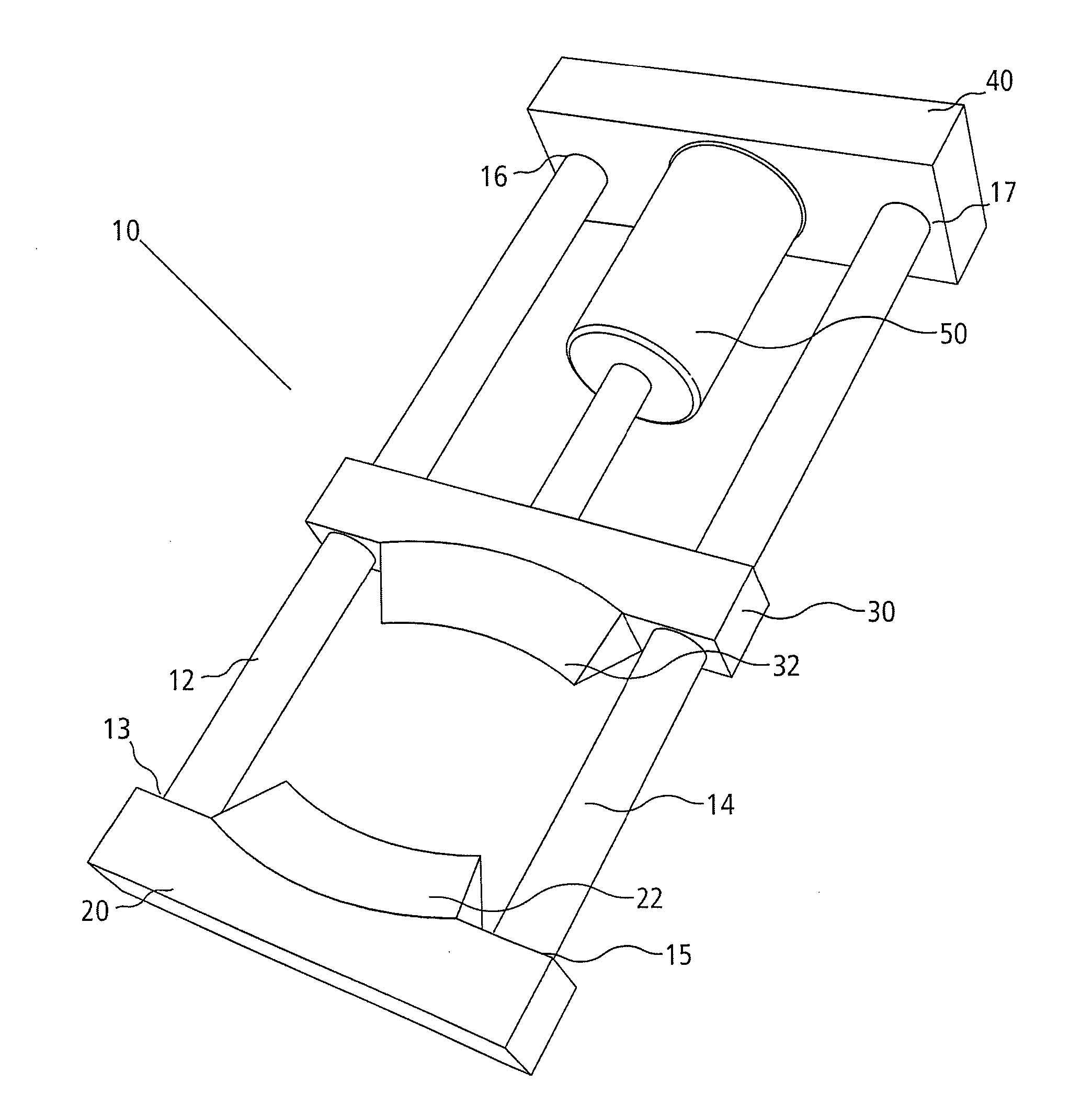
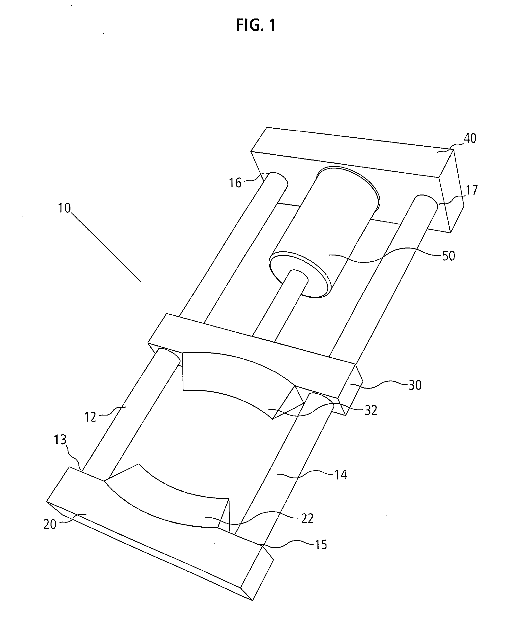
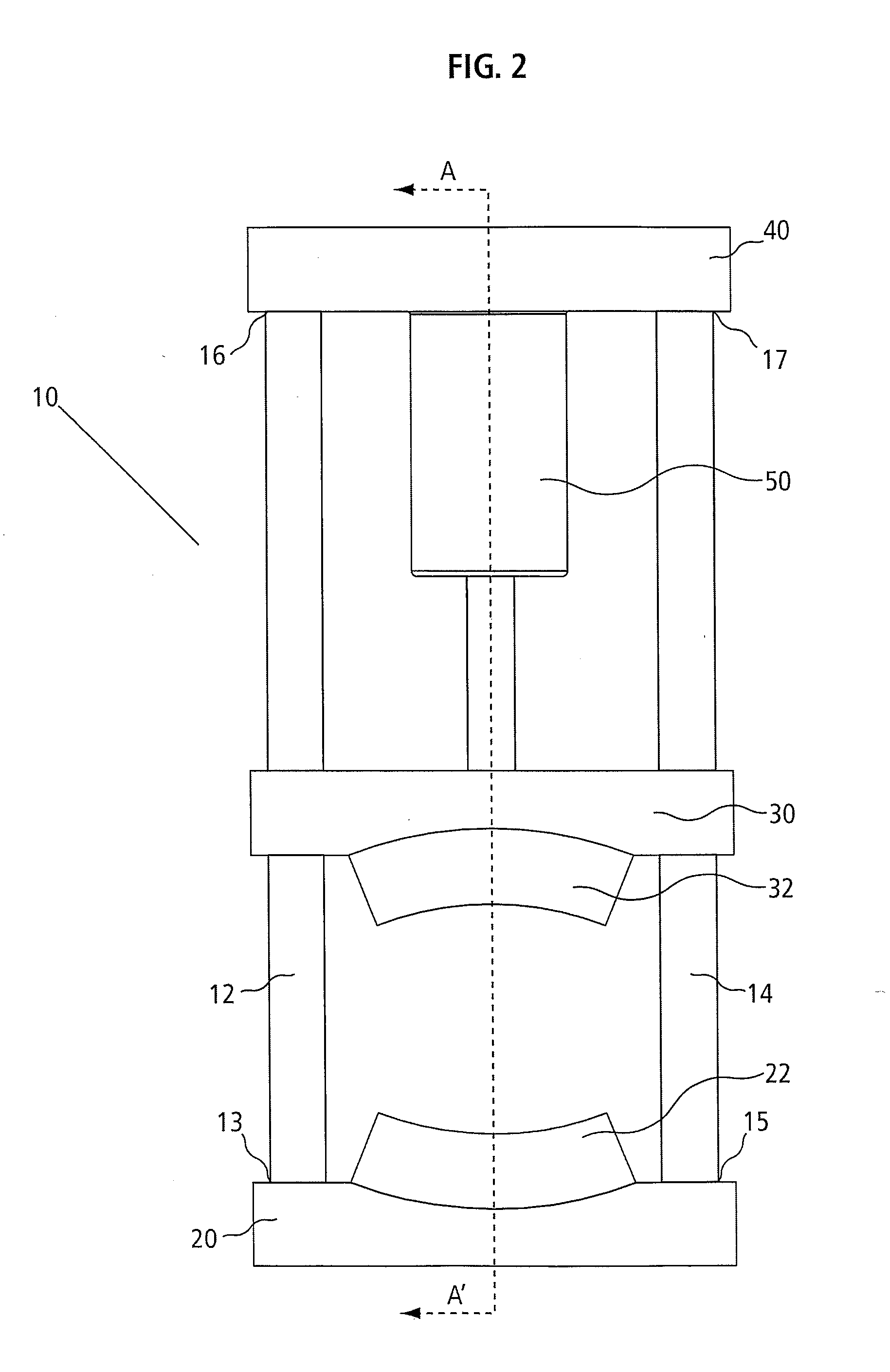
[0024]FIGS. 1 and 2 illustrate a crusher tooth removal tool 10. The crusher tooth removal tool 10 uses a double wedge action to remove a crusher tooth from a crusher roll segment. A pair of substantially parallel guide members 12, 14 are provided with a first wedge assembly 20 attached to first ends 13, 15 of the guide members 12, 14, respectively, so that the first wedge assembly 20 will not move relative to the guide members 12, 14. The wedge assembly 20 has a first wedge 2...


PUM

PropertyMeasurementUnit
Forceaaaaaaaaaa
Shapeaaaaaaaaaa

Abstract

A crusher tooth removal tool is provided having a guide comprising a pair of substantially parallel elongate guide members, said guide having a first end and a second end; a first wedge assembly attached at or near the first end of the guide, said first wedge assembly having a first wedge; a second wedge assembly having a second wedge, said second wedge assembly slideably attached to the guide so that the second wedge and the first wedge are facing each other; a brace fixedly attached at or near the second end of the guide; and a force exerting device connected between the second wedge assembly and the brace such that the force exerting device is operative to force the second wedge assembly along the guide towards the first wedge assembly.

Description

[0001]This application claims priority to U.S. provisional patent application No. 61 / 100,366, filed Sep. 26, 2008.FIELD OF INVENTION[0002]The present invention relates to an apparatus and method for the removal of crusher teeth used in a crusher.BACKGROUND OF THE INVENTION[0003]Oil sand is a type of bitumen deposit typically containing sand, water and very viscous oil (the bitumen). One method of extracting oil sand from an oil sands deposit, when the oil sand deposit is located relatively close below the ground surface, is through mining. This method entails excavating down through the ground surface to where the oil sand deposit occurs and removing oil sand from the deposit with heavy machinery. Typically, this removal of the oil sand from the deposit is done with some of the largest power shovels and dump trucks in the world, with the power shovels removing shovel-loads of oil sand from the deposit and loading the collected oil sand onto dump trucks to be carried away for further...

Claims


Application Information

Patent Timeline
IPC IPC(8): B23P19/04
CPCB02C4/08Y10T29/53Y10T29/49822B02C4/28
Inventor SANVALIYA, YOGESHKEAYS, GARY
Owner SYNCRUDE CANADA LTD
Why Eureka
Try Eureka