Engine Unit and Vehicle Comprising Engine Unit

a technology of engine unit and engine body, which is applied in the direction of combustion engines, machines/engines, mechanical equipment, etc., can solve the problems of difficult cooling of engine bodies, and achieve the effects of reducing the vibration of the main body, preventing thermal deformation, and facilitating engine cooling

Active Publication Date: 2010-04-01
KAWASAKI MOTORS LTD
View PDF8 Cites 353 Cited by
  • Summary
  • Abstract
  • Description
  • Claims
  • Application Information

AI Technical Summary

Benefits of technology

[0005]The present invention addresses the above described conditions, and an object of the present invention is to reduce a vibration of a main body of a supercharging machine, to prevent a thermal deformation of the main body of the supercharging machine and a thermal deformation of an engine body from affecting each other, and to facilitate cooling of an engine.
[0007]In accordance with such a configuration, since the vibration of the engine is absorbed by the component or the member disposed between the main body of the supercharging machine and the engine body, it is less likely to be transmitted to the supercharging machine. In addition, thermal deformation of the main body of the supercharging machine is absorbed by the component or the member. Furthermore, since the heat of the main body of the supercharging machine is not directly transmitted to the engine body, cooling of the engine body is facilitated.
[0009]In accordance with such a configuration, since the heat of the main body of the supercharging machine is blocked by the passage member and is less likely to be transmitted to the engine body, cooling of the engine is facilitated.

Problems solved by technology

Furthermore, since the heat tends to be transferred from the main body of the supercharging machine to the engine body, it is difficult to cool the engine body.

Method used


Image

  • Engine Unit and Vehicle Comprising Engine Unit
  • Engine Unit and Vehicle Comprising Engine Unit
  • Engine Unit and Vehicle Comprising Engine Unit

Examples


embodiment 1

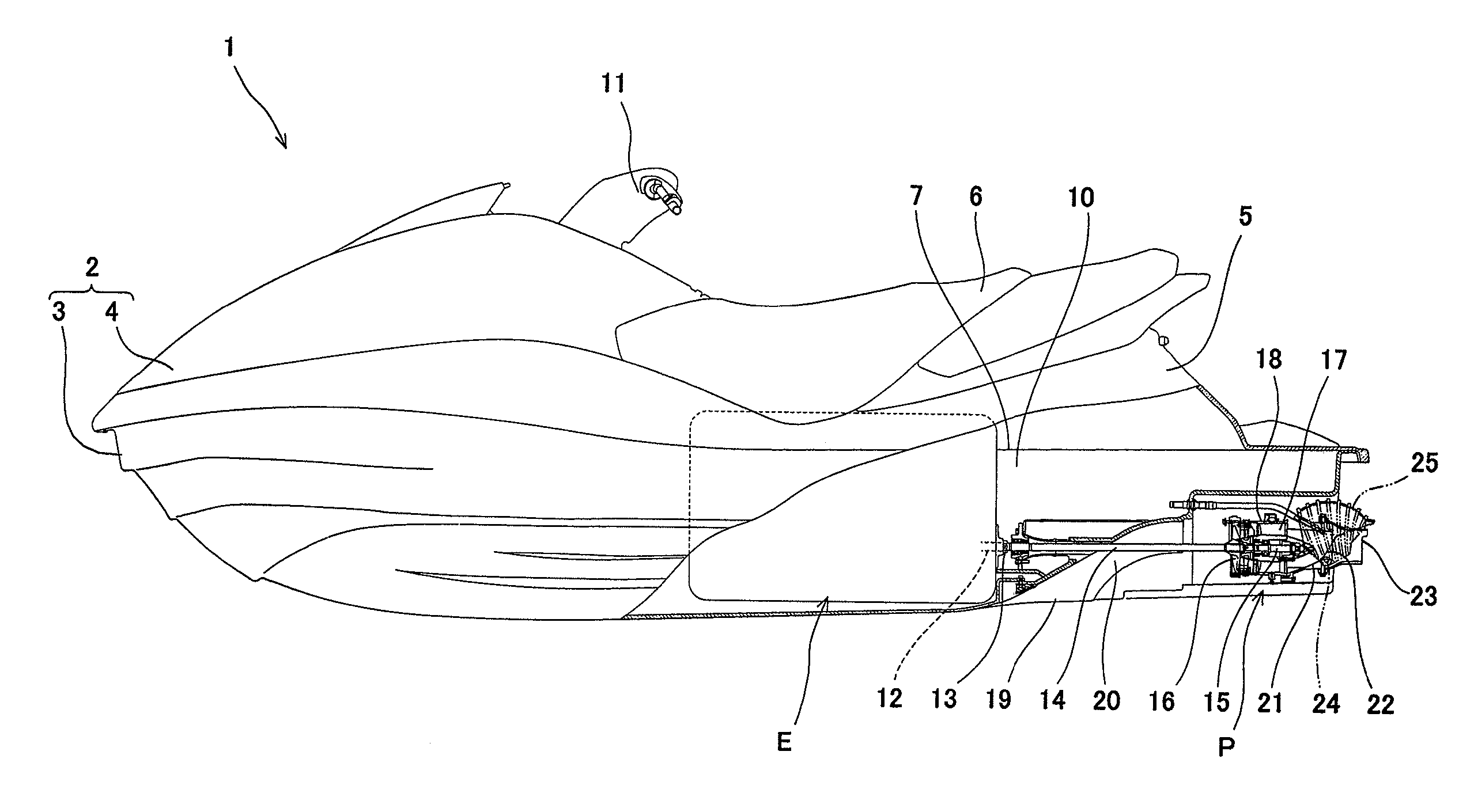
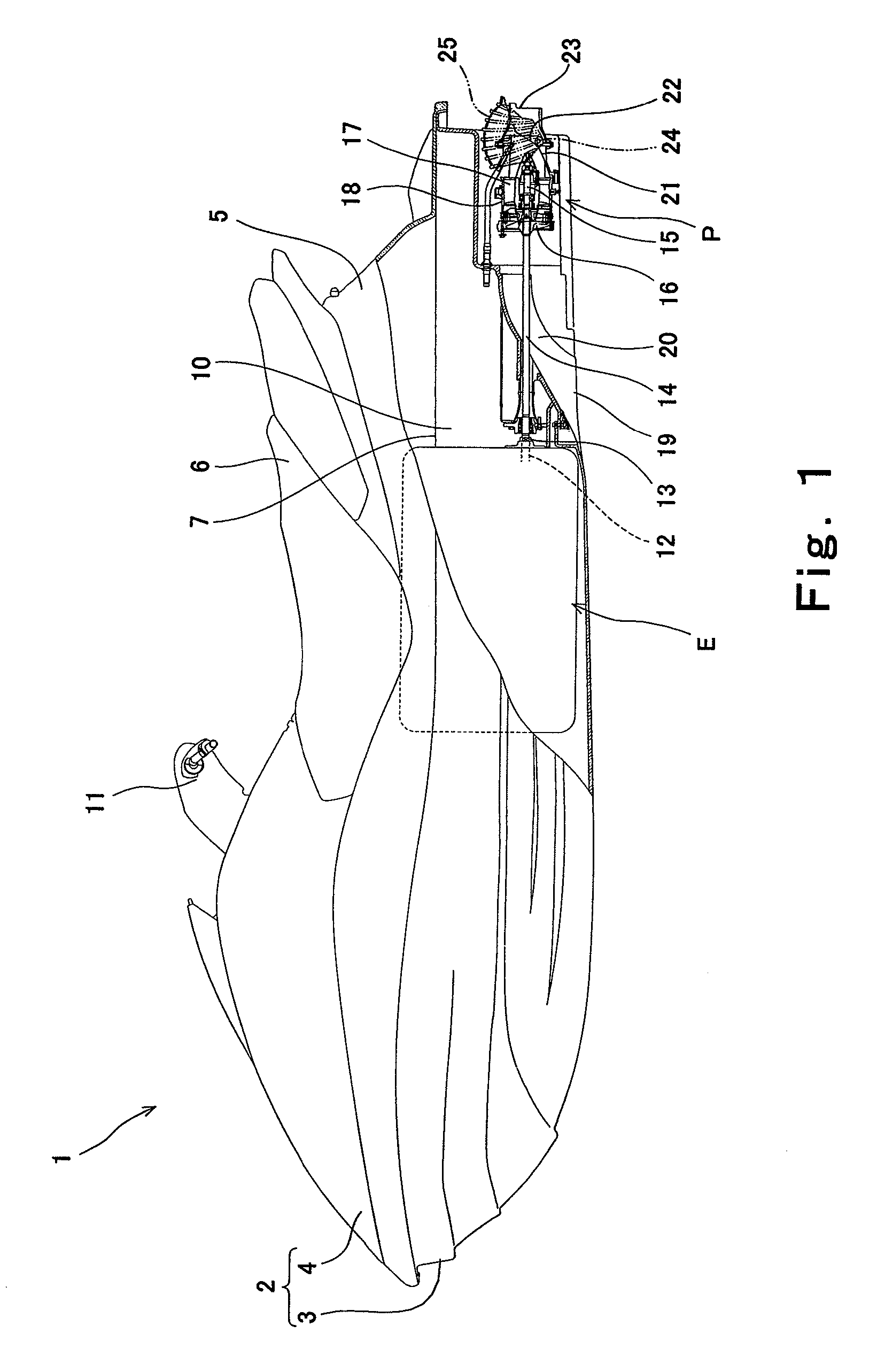
[0020]FIG. 1 is a cross-sectional view of a personal watercraft 1 according to the embodiment of the present invention, a part of which is cut away, as viewed from the left. Turning now to FIG. 1, the personal watercraft 1 of FIG. 1 is a straddle-type jet-propulsion personal watercraft which is provided with a seat 6 straddled by the rider. A body 2 of the watercraft 1 includes a hull 3 and a deck 4 covering the hull 3 from above. A center section in a width direction protrudes upward at a rear part of the deck 4 to form a protruding portion 5. The seat 6 is mounted over an upper surface of the protruding portion 5. A deck floor 7 is formed at both sides in the width direction of the protruding portion 5 to be substantially flat and lower than the protruding portion 5 to enable the rider to put feet thereon.

[0021]A space defined by the hull 3 and the deck 4 below the seat 6 is an engine room 10 in which an engine unit E is mounted. A crankshaft 12 of the engine unit E extends along ...

embodiment 2

[0055]FIG. 6 is a plan view showing a schematic configuration of an engine unit E2 according to a second embodiment of the present invention. As shown in FIG. 6, the engine unit E2 includes an engine 130 and a supercharging machine 150. A main body 151 of the supercharging machine 150 is disposed on the left side of an engine body 131 of the engine 130.

[0056]A side cover 162 is coupled to a right side surface of the main body 151. An intake duct 161 extends forward from a front surface of the side cover 162. The intake duct 161 is coupled to an air box which is not shown. In this construction, the air from the air box is delivered to the interior of the main body 151 of the supercharging machine 150 via the intake duct 161 and the interior of the side cover 162. Thus, the side cover 162 forms a part of passage members forming an air passage through which the air flows to the supercharging machine 150.

[0057]A discharge duct 182 is coupled to an upper surface of the main body 151. The...

embodiment 3

[0060]FIG. 7 is a plan view showing a schematic configuration of an engine unit E3 according to a third embodiment of the present invention. As shown in FIG. 7, the engine unit E3 includes an engine 230 and a supercharging machine 250. A main body 251 of the supercharging machine 250 is disposed on the left side of an engine body 231 of the engine 230.

[0061]An intake duct 261 extends forward from a front surface of the main body 251 of the supercharging machine 250. The intake duct 261 is coupled to the air box (not shown). In this construction, the air from the air box is delivered to the interior of the main body 251 via the intake duct 261. A discharge duct 282 is coupled to an upper surface of the main body 251. The discharge duct 282 extends to the right above the main body 251 and is coupled to an intercooler 283. Thereby, the air, which has been compressed within the main body 251, is delivered to the intercooler 283 via the discharge duct 282. A tensioner unit (not shown) is...


PUM


Abstract

An engine unit includes an engine body, and a supercharging machine having a main body. The main body of the supercharging machine is coupled to the engine body via a component or a member disposed therebetween.

Description

TECHNICAL FIELD[0001]The present invention relates to an engine unit comprising a supercharging machine, and a vehicle comprising the engine unit.BACKGROUND ART[0002]As disclosed in Japanese Laid-Open Patent Application Publication No. 2007-247518, an engine unit mounted in a vehicle such as personal watercraft sometimes includes a supercharging machine such as a mechanical supercharger or a turbo charger (exhaust turbine supercharger).[0003]Typically, a main body of the supercharging machine is directly mounted to a side surface of an engine body. In such a construction, since a vibration of the engine is directly transmitted to the main body of the supercharging machine, it is necessary to increase stiffness of the main body of the supercharging machine and resistance of components within the main body to the vibration.[0004]During running of the engine, typically, a temperature of the main body of the supercharging machine tends to be higher than a temperature of the engine body,...

Claims


Application Information

Patent Timeline
Patent Type & Authority Applications(United States)
IPC IPC(8): F02B33/00
CPCF02B33/40F02B29/045F02B29/0475
Inventor ARAKI, TOSHIO
Owner KAWASAKI MOTORS LTD
Why Eureka
Try Eureka