
Biosensor

Active Publication Date: 2010-04-01
PHC HLDG CORP
View PDF8 Cites 14 Cited by
  • Summary
  • Abstract
  • Description
  • Claims
  • Application Information

AI Technical Summary

Benefits of technology

[0020]According to the present invention, since a biosensor which has a capillary structure and performs measurement with a very small quantity of sample is constituted as described above, even when a sample supply port is closed up by elastic skin such as fingertip, brachial region, or abdominal region of a test subject, it is possible to perform reliable aspiration of the sample solution from an auxiliary sample supply port into the capillary.

Problems solved by technology

In this biosensor, however, there is a possibility that the blood is not successfully introduced into the capillary depending on the angle of the biosensor when the blood is applied onto the sample supply port, and thereby the blood might be attached to the outer surface of the insulating substrate by mistake.
In this case, even when the user tries to supply the blood again, the blood attached to the outer surface impedes the user from successfully supplying the blood into the capillary, resulting in faulty measurement and measurement errors.

Method used


Image

  • Biosensor
  • Biosensor
  • Biosensor

Examples


embodiment 1

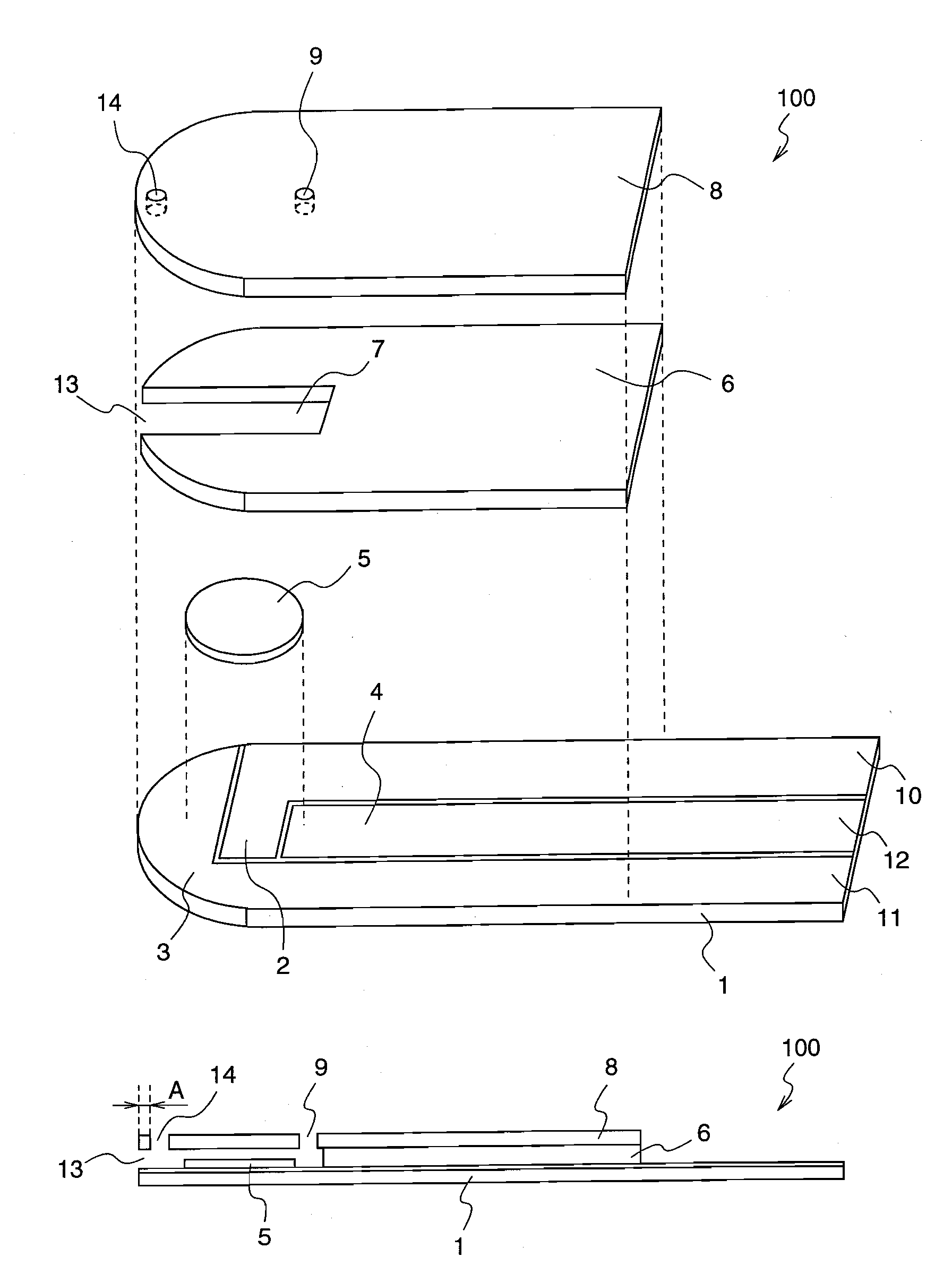
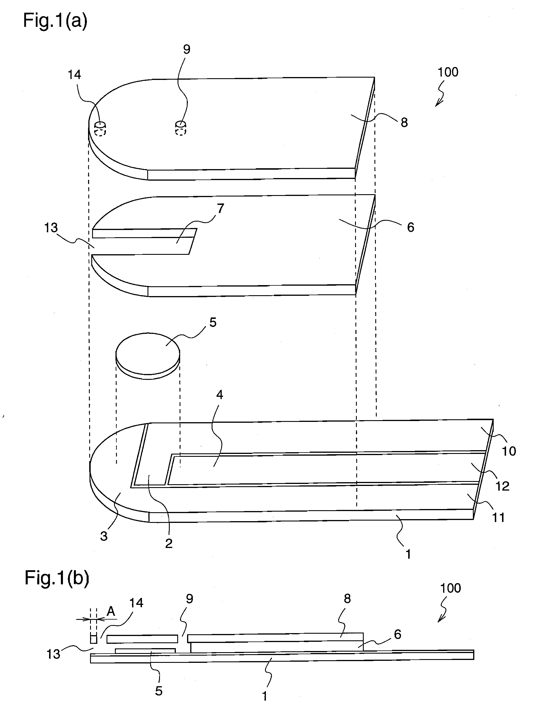
[0057]FIG. 1 illustrates an exploded perspective view and a cross-sectional view of a biosensor 100 according to a first embodiment of the present invention.

[0058]In the biosensor 100 shown in FIG. 1, reference numeral 1 denotes a first insulating substrate having a portion near a front end being formed approximately in a semicircular shape, and a portion that follows the front end to reach an rear end being formed in a rectangle. A measurement element 2, a counter electrode 3, and a detector electrode 4 which are composed of an electric conducting material are formed on the first insulating substrate 1. Reference numeral 8 denotes a second insulating substrate which is formed in a shape similar to that of the first insulating substrate 1, reference numeral 6 denotes a spacer which is disposed between the first insulating substrate 1 and the second insulating substrate 8 and is formed in a shape similar to those of the both insulating substrates, and reference numeral 7 denotes a ca...

embodiment 2

[0094]FIG. 5 illustrates an exploded perspective view and a cross-sectional view of a biosensor 500 according to a second embodiment of the present invention.

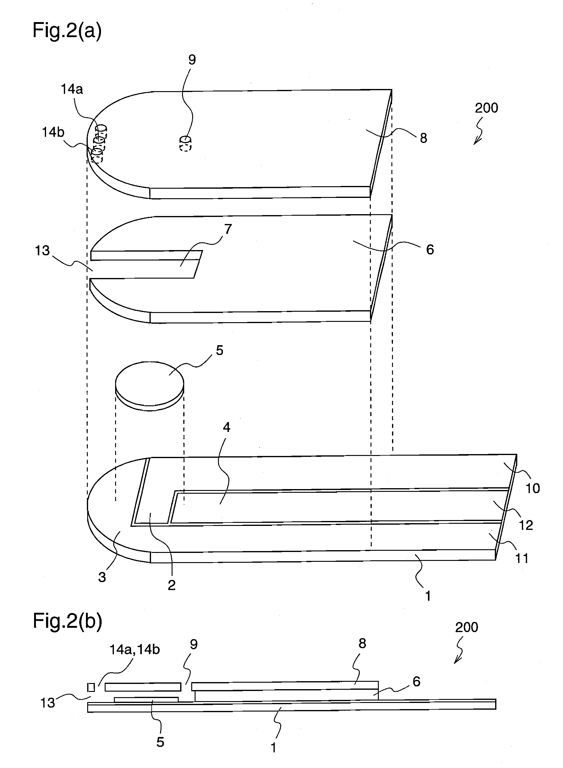
[0095]In the biosensor 500 of the second embodiment shown in FIG. 5, auxiliary sample supply ports 14 are provided on both the first insulating substrate 1 and the second insulating substrate 8.

[0096]Since the auxiliary sample supply ports 14 are provided on the two insulating substrates 1 and 8, respectively, even if the sample is applied from a biased angle, the sample can be reliably aspirated into the space 6.

[0097]Further, as described in the first embodiment, plural auxiliary sample supply ports 14 may be provided on the respective substrates with the same effects as mentioned above.

[0098]Further, the shape of the auxiliary sample supply port 14 is not particularly restricted, and it may be circular, oval, linear, rectangular, or triangular.

embodiment 3

[0099]FIG. 6 illustrates an exploded perspective view and a cross-sectional view of a biosensor 600 according to a third embodiment of the present invention.

[0100]In the biosensor 600 of the third embodiment shown in FIG. 6, the capillary 7 branches in a Y shape in the vicinity of the front end, and one of the branches serves as the sample supply port 13 while the other serves as the auxiliary sample supply port 14.

[0101]In this third embodiment, since the spacer 6 is provided with the two sample supply ports, the same effects as those of the first and second embodiments are achieved. Further, since the sample supply port 13 and the auxiliary sample supply port 14 can be simultaneously patterned in the spacer 6, the number of process steps in the sensor fabrication can be reduced.

[0102]Hereinafter, a specific example of the present invention will be described in detail.

[0103]A biosensor constituted as mentioned below is used as an example.

[0104]After a palladium thin film having a t...


PUM

PropertyMeasurementUnit
Areaaaaaaaaaaa
Distanceaaaaaaaaaa
Volumeaaaaaaaaaa

Abstract

It is an object of the present invention to provide an excellent biosensor which can perform supply of a sample solution accurately and easily. A biosensor which has a capillary (7) for collecting a sample solution and analyzes a specific substance in the sample solution is provided with, in addition to an air hole (9), at least two supply ports, i.e., a sample supply port (13) and an auxiliary sample supply port (14), so that supply of the sample solution can be performed from either of the supply ports (13) and (14). Even when the sample supply port (13) is closed up with a fingertip or the like and supply of the sample solution is stopped, the sample solution can be quickly supplied from the other auxiliary sample supply port (14).

Description

TECHNICAL FIELD[0001]The present invention relates to a biosensor for analyzing a specific component in a sample solution, and more particularly, to a biosensor which collects a small amount of sample solution by capillary phenomenon onto a small-size test specimen, and analyzes the sample solution.BACKGROUND ART[0002]A biosensor is a sensor for determining a quantity of a base substance in a sample solution, which utilizes a molecule recognizing ability of a biological material such as micro-organism, enzyme, antibody, DNA, RNA or the like to employ the biological material as a molecule discrimination element. To be specific, the biosensor determines a quantity of a base substance contained in a sample solution by utilizing a reaction which occurs when a biological material recognizes an objective substrate, such as consumption of oxygen due to respiration of a micro-organism, enzyme reaction, light emission, and the like. Among various kinds of biosensors, an enzyme sensor has com...

Claims


Application Information

Patent Timeline
IPC IPC(8): G01N27/26G01N1/10
CPCG01N27/3272G01N27/327G01N33/48
Inventor YAMANISHI, ERIKOTOKUNAGA, HIROYUKIHIGASHIHARA, AKIHISA
Owner PHC HLDG CORP
Features
  • Generate Ideas
  • Intellectual Property
  • Life Sciences
  • Materials
  • Tech Scout
  • Unparalleled Data Quality
  • Higher Quality Content
  • 60% Fewer Hallucinations
Learn More