Fluid overfill probe with thermal stress prevention

a technology of thermal stress prevention and overfill probe, which is applied in the direction of liquid/fluent solid measurement, instruments, machines/engines, etc., can solve the gap between the circuit components and surrounding solid materials in the housing

Active Publication Date: 2010-04-01
SCULLY SIGNAL CO
View PDF10 Cites 3 Cited by
  • Summary
  • Abstract
  • Description
  • Claims
  • Application Information

AI Technical Summary

Benefits of technology

[0010]To create a desired gap, free of solid material, a receptacle may be used that is located within the housing and surrounds the circuit board. The receptacle may be a tube that is fixed in position relative to the housing, for example, by a potting material that surrounds the tube and cures to a rigid state. The circuit board may be positioned adjacent to an inner surface of the tube along its edges. In such a configuration, the edges of the circuit board may make contact with the tube, preventing movement of the circu...

Problems solved by technology

However, the mounting of the circuit board is such that a gap exists b...

Method used


Image

  • Fluid overfill probe with thermal stress prevention
  • Fluid overfill probe with thermal stress prevention
  • Fluid overfill probe with thermal stress prevention

Examples


Embodiment Construction

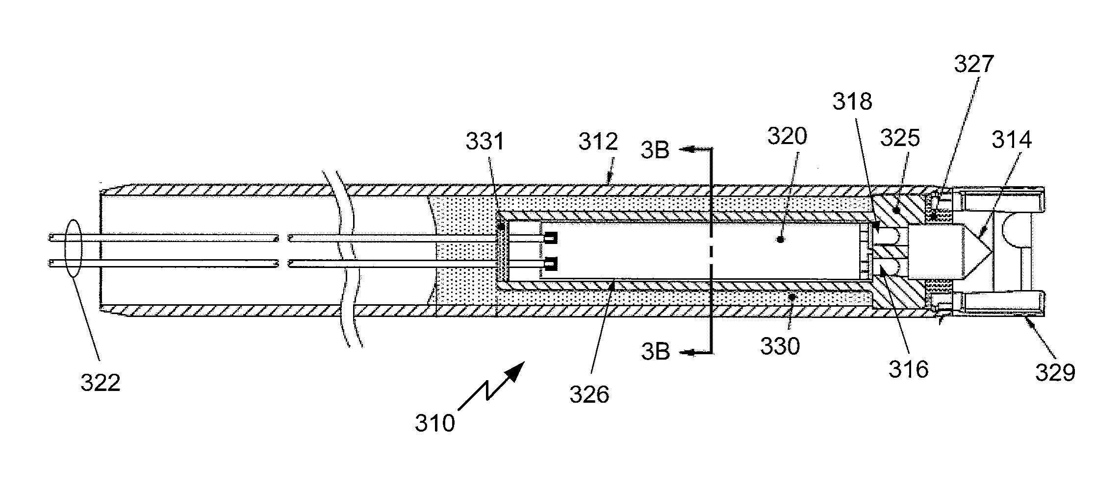
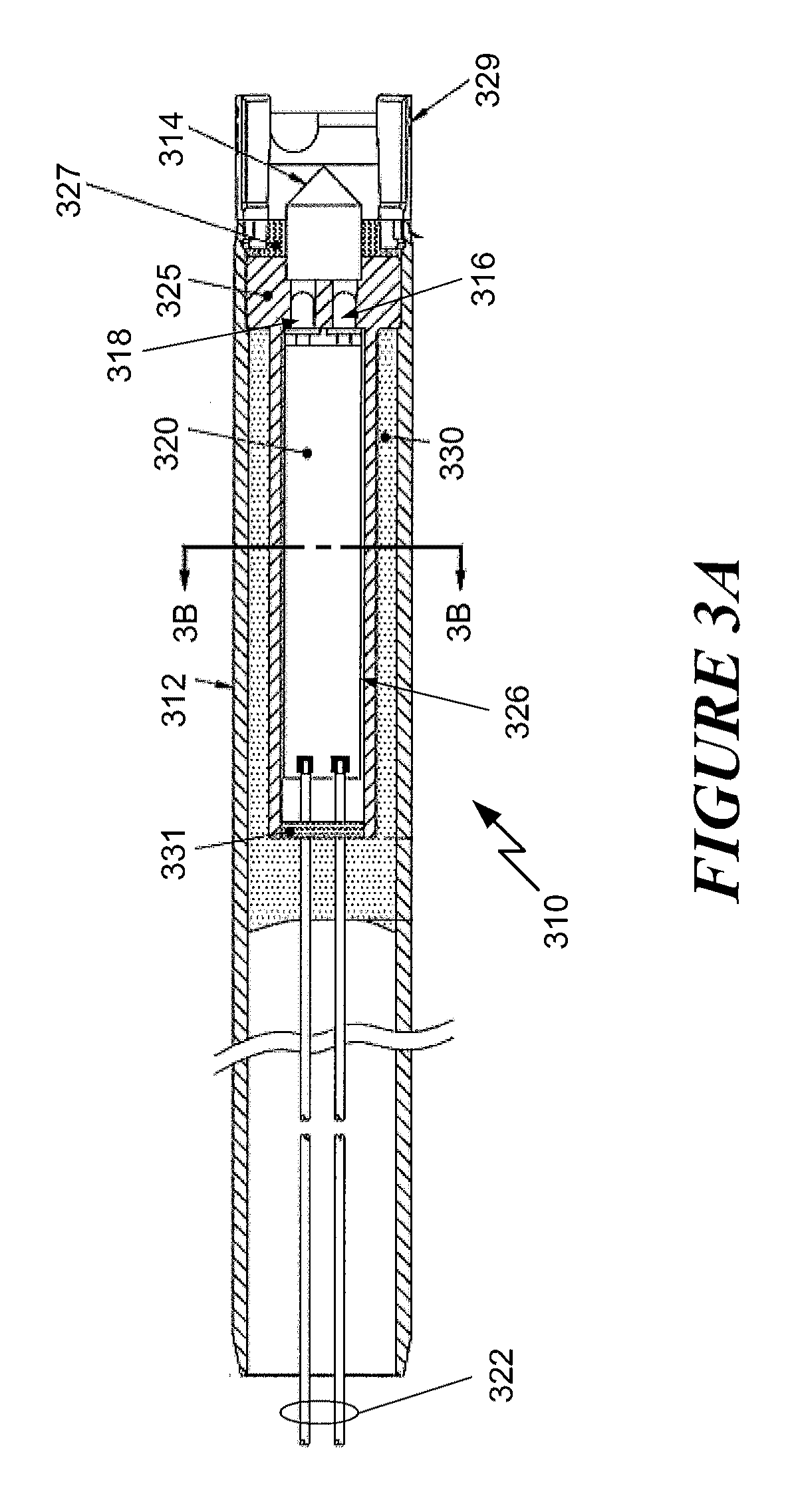
[0016]Shown in FIG. 3A is a cross-sectional side view of an overfill probe 310 according to an exemplary embodiment of the present invention. The probe components are encased in a housing 312 of a durable material, preferably a light metal such as aluminum. A prism 314 is located at a first end of the probe that faces the liquid being monitored in a fluid compartment. Adjacent to the prism is light emitting diode (LED) light source 316 and a photodetector 318. As discussed above, an optical signal generated by the light source 316 is coupled into the prism 314 in the direction of the prism surfaces that are contacted by the fluid when the compartment is full. Thus, the signal from the light source is internally reflected and detected by the photodetector when the fluid level is below the position of the probe, due to the large difference in the indexes of refraction of the prism material and the surrounding air. If the fluid level reaches the probe, the refractive index difference i...


PUM


Abstract

A fluid overfill probe is resistant to failure caused by physical stresses resulting from thermal expansion of probe components. A fluid level detector is connected to circuit components that are mounted on a circuit board located in a housing of the probe. The circuit board is located within a tube that is positioned within, and secured to the housing, and the circuit board is secured to an inner surface of the tube along its edges. The tube has a shape and rigidity sufficient to maintain a gap between the circuit components and the inner surface of the tube such that thermal expansion of probe components result in no physical stress to the circuit components.

Description

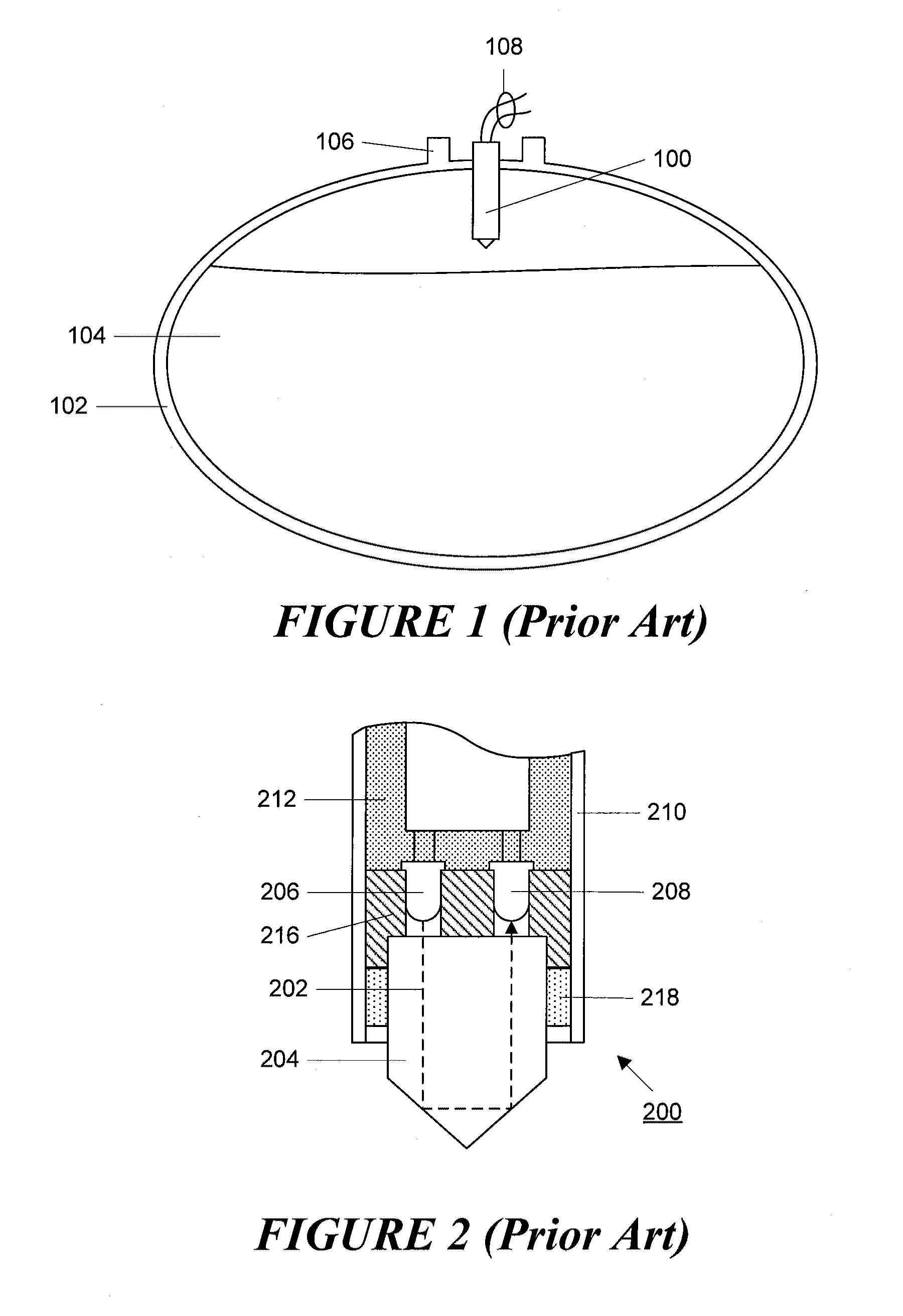
FIELD OF THE INVENTION[0001]This invention relates to fluid control apparatus and, particularly, to optical overfill probes that detect when fluid being transferred into a container has exceeded a desired maximum level and provide a signal used to prevent overfill of the container.BACKGROUND OF THE INVENTION[0002]In the art of fluid transfer control, particularly as it applies to the petroleum industry, one of the more common control devices is an overfill sensor for determining when the fluid being transferred into a container, such as a petroleum tanker truck compartment, has exceeded a predetermined level. An output signal from such a probe indicates an overfill risk, and may be used by a fluid transfer controller to discontinue fluid flow into the compartment. In this way, overfilling of the compartment, which is particularly hazardous when dealing with flammable liquids such as gasoline, can be avoided. Such a probe 100 is shown schematically in FIG. 1, which shows a partial cr...

Claims


Application Information

Patent Timeline
IPC IPC(8): G01F23/292
CPCG01F23/2925
Inventor TROTTIER, ROBERT R.
Owner SCULLY SIGNAL CO
Why Eureka
Try Eureka