
Microwave system calibration apparatus and method of use

Active Publication Date: 2010-04-01
TYCO HEALTHCARE GRP LP
View PDF57 Cites 52 Cited by
  • Summary
  • Abstract
  • Description
  • Claims
  • Application Information

AI Technical Summary

Benefits of technology

[0013]In yet another embodiment the body may includes a positioner to position the microwave energy delivery device in a fixed position relative to the chamber. The positioner on the body may correspond to a substantially similar interface on the microwave energy device. The positioner and the interface may mate with each other to

Problems solved by technology

Efficiency of energy delivery decreases when the impedance of any portion of the system changes.
Obtaining accurate measurements of tissue impedance at microwave frequencies is more difficult because circuits behave differently at microwave frequency.
As such, it is difficult to determine what percentage of the energy generated by the microwave generator is actually delivered to tissue, and conventional algorithms for tissue impedance are inaccurate.
While this is a generally accepted method, this method can also prove to be inaccurate because the method fails to account component losses and depends on indirect measurements, such as, for example forward and reflected power measurements from directional couplers, to calculate impedance.
In addition, this method does not provide information related to phase, a component vital to determining antenna impedance.
Unfortunately, this equipment is prone to damage by high power signals and the microwave energy delivery system typically needs to be reconfigured to accommodate and protect such equipment.

Method used


Image

  • Microwave system calibration apparatus and method of use
  • Microwave system calibration apparatus and method of use
  • Microwave system calibration apparatus and method of use

Examples


Embodiment Construction

[0032]Detailed embodiments of the present disclosure are described herein; however, it is to be understood that the disclosed embodiments are merely exemplary and may be embodied in various forms. Therefore, specific structural and functional details disclosed herein are not to be interpreted as limiting, but merely as a basis for the claims and as a representative basis for teaching one skilled in the art to variously employ the present disclosure in virtually any appropriately detailed structure.

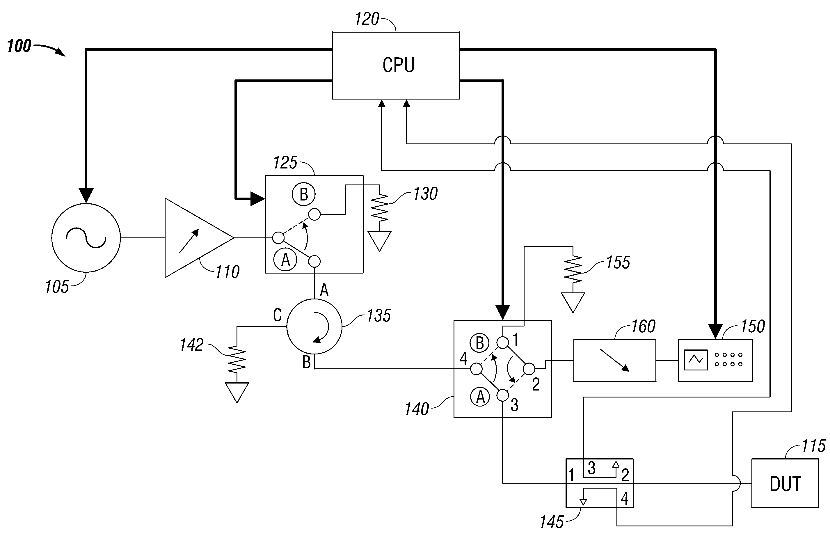
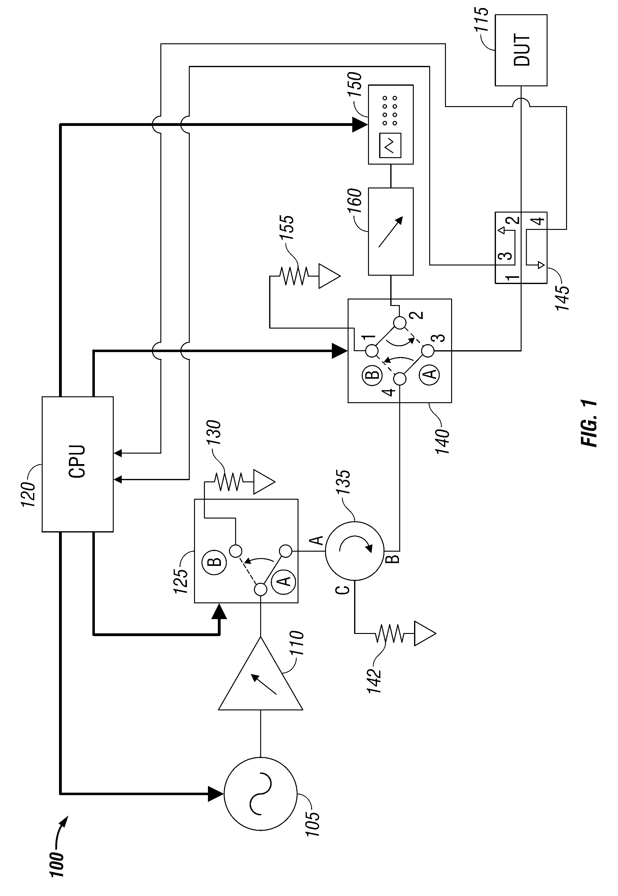
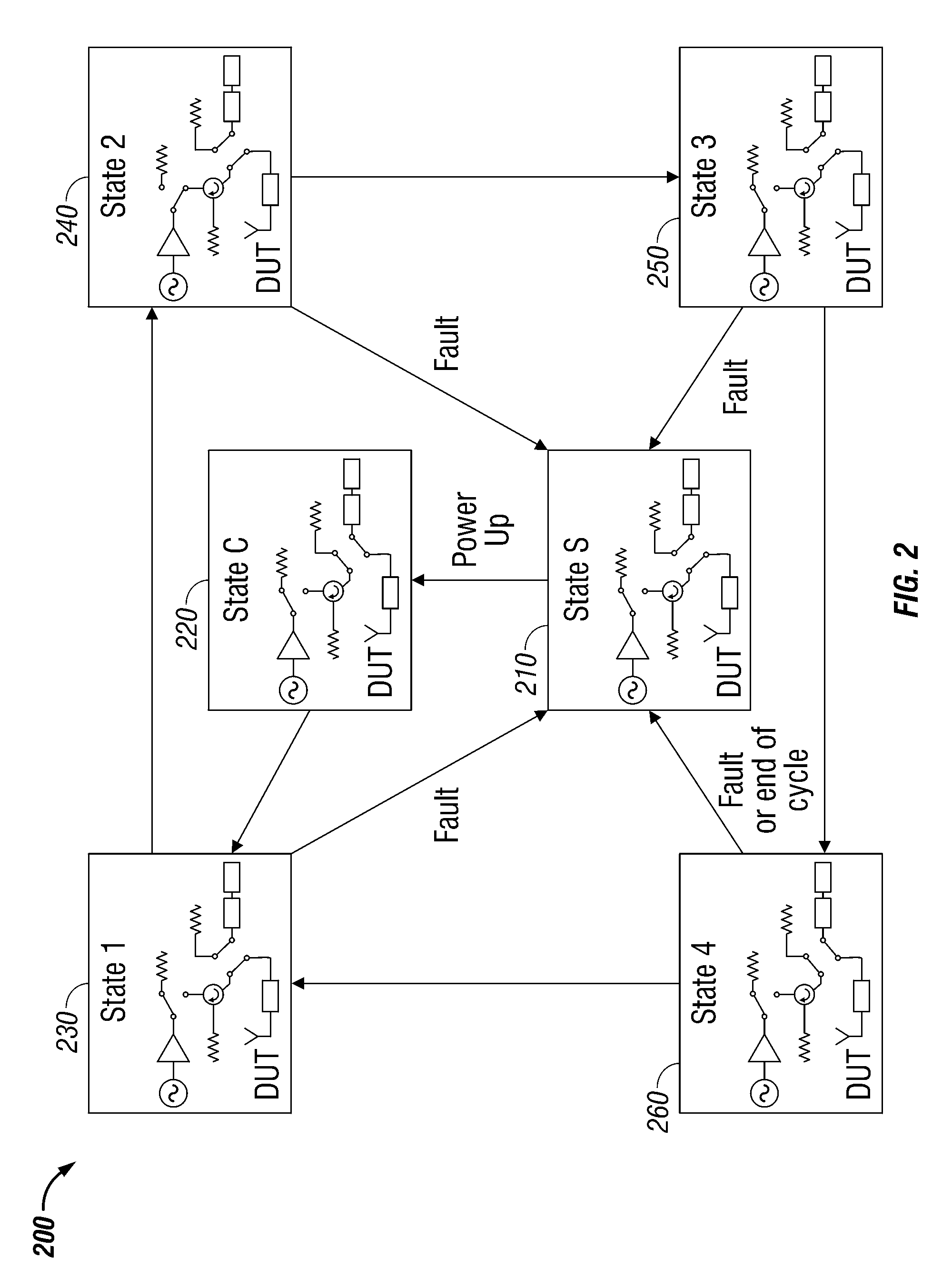
[0033]Referring to FIG. 1, a Microwave Research Tool (MRT) including a measurement and control system for use in performing a medical procedure or medical procedure testing, employing embodiments of the present disclosure is generally designated 100. MRT 100 may provide all the functionality of a microwave generator typically used to deliver microwave energy in a medical procedure but with improved functionality as described herewithin. MRT 100 includes individual components, as illustrate...


PUM


Abstract

An apparatus for calibrating a microwave energy delivery device including a body, the body defining a chamber portion. The chamber portion is configured to receive a portion of a microwave energy delivery device and the body is configured to absorb energy transmitted by the microwave energy delivery device at a predetermined absorption rate.

Description

BACKGROUND[0001]1. Technical Field[0002]The present invention relates to systems and methods for performing a medical procedure, wherein the medical procedure includes the generation and transfer of energy from an energy source to a dynamically changing device and, more particularly, efficient transfer of energy through a microwave energy delivery, measurement and control system.[0003]2. Description of Related Art[0004]During microwave ablation procedures, the electrical performance of a microwave antenna probe changes throughout the course of an ablation treatment. The change in performance may be due to the device or due to changes in tissue properties. The ability to observe parameters indicative of changes in antenna property, antenna performance or tissue properties changes during ablation greatly aids in the understanding of microwave ablation. For example, measuring antenna impedance is a common method for determining antenna performance and / or a change in an antenna property...

Claims


Application Information

Patent Timeline
IPC IPC(8): A61F2/00
CPCA61B18/18A61N5/02A61B18/1815
Inventor BRANNAN, JOSEPH D.PAULUS, JOSEPH A.
Owner TYCO HEALTHCARE GRP LP
Learn More