Fiber optic gas sensor

a gas sensor and fiber optic technology, applied in the field of sensors, can solve the problems of inability to actively adjust and/or reconfigure once deployed, inconvenient packaging, passive in-fiber optic components, etc., and achieve the effects of improving sensitivity and response time, reducing the strain on the optical fiber, and increasing the gas absorption ra

Active Publication Date: 2009-05-21
UNIVERSITY OF PITTSBURGH +1
View PDF8 Cites 47 Cited by
  • Summary
  • Abstract
  • Description
  • Claims
  • Application Information

AI Technical Summary

Benefits of technology

[0013]The present invention, in one embodiment, provides a sensor for sensing a gas, such as hydrogen, that includes an optical fiber having a core and a wavelength resonant in-fiber optic component, such as a fiber Bragg grating or Fabry-Perot filter, provided in the core at a first location. The optical fiber propagates a sensing light and a power light, with the sensing light being propagated in the core. The wavelength resonant in-fiber optic component receives the sensing light and reflects a reflected light having a resonance wavelength that is dependent on a characteristic, such as a grating spacing, of the wavelength resonant in-fiber optic component. The reflected light is used to determine at least one of a presence of and a concentration of the gas. In addition, at least one layer of a certain material is attached to the optical fiber in proximity to the first location. In particular, the material is a material, such as palladium or a palladium alloy, that is able to absorb the gas being sensed (e.g., hydrogen) at a temperature dependent gas absorption rate that increases when a temperature of the material is increased up to some limiting high temperature that is dependent on environmental conditions. The material induces a strain in the optical fiber when the material absorbs the gas, with a magnitude of the strain being dependent upon an amount of the gas that is absorbed. The strain in the optical fiber changes the characteristic, e.g., grating spacing. Finally, the optical fiber is structured to allow at least a portion of the power light to be used to heat the material. In one particular embodiment, the optical fiber is structured to allow at least a portion of the power light to be released from the optical fiber at the first location and be absorbed by the material. In another embodiment, at least a portion of the power light may be absorbed by another portion of the fiber, such as the inner or out cladding, generate heat that in turn heats the material. The absorbed power light heats the material and increases the gas absorption rate. As a result, the sensitivity and response time of the sensor is improved, particularly at low temperatures.

Problems solved by technology

Historically, in-fiber optic components have been passive, meaning they cannot be actively adjusted and / or reconfigured once deployed to, for example, adopt new network topologies or adjust sensing parameters including sensitivity, set point, triggering time, dynamic range and responsivity.
In addition, passive in-fiber optic components require delicate and costly packaging to eliminate temperature drifting.
These facts have, despite the advantages described above, limited the performance and use of in-fiber components.
The problem has been that each of these tuning mechanisms requires an energy source for operation, which, to date, has been electrical.
Additional cabling of this sort is problematic, as it, among other things, typically increases manufacturing costs, is bulky, is not immune to electromagnetic radiation, is difficult to embed in materials and structures, and typically has a shorter lifetime than the associated, normally durable optical fibers.
Unfortunately, the use of highly flammable liquid H2 also introduces a number of safety concerns due to its rapid evaporation rate and low explosive limit.
Although a number of sensing solutions have been developed based on the use of a Pd-coating as described above, those solutions share a common problem, namely, due to palladium's slow hydrogen absorption rate at low temperature (e.g., on the order of 20 degrees C. and lower), the sensors exhibit an extremely low sensitivity and slow response time at low temperatures.

Method used


Image

  • Fiber optic gas sensor
  • Fiber optic gas sensor
  • Fiber optic gas sensor

Examples


Embodiment Construction

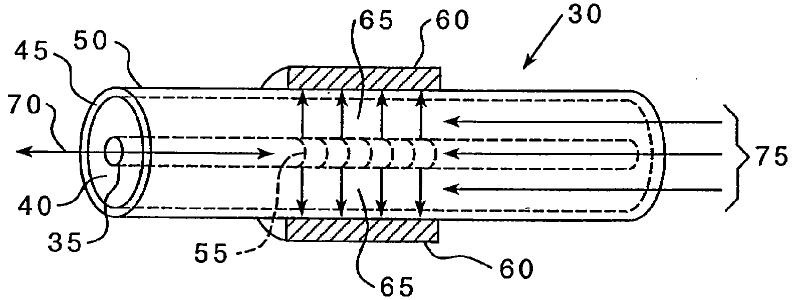
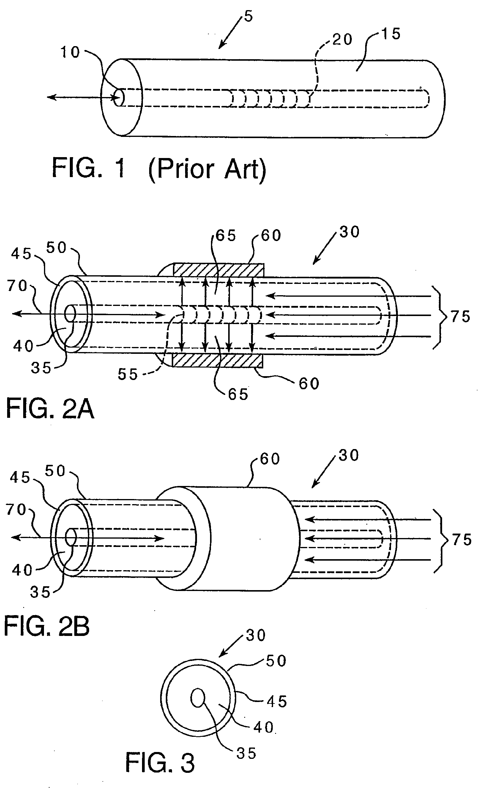
[0043]The present invention relates to various systems and methods for providing active in-fiber optic components that are powered by in-fiber light. Specifically, as described in greater detail herein, various optical fibers are provided that propagate both a sensing or signal light and a power light wherein the power light is used to provide the energy required to tune the in-fiber optic component.

[0044]FIGS. 2A and 2B are side views (2A in partial cross-section) and FIG. 3 is a cross-sectional end view of optical fiber 30 according to one embodiment of the present invention. As seen most readily in FIG. 3, optical fiber 30 includes a core 35, inner cladding 40, outer cladding 45 and protective layer 50. Preferably, core 35, inner cladding 40 and outer cladding 45 are made of light propagating materials, wherein core 35 has an index of refraction that is greater than the index of refraction of inner cladding 40, which in turn is greater than the index of refraction of outer claddi...


PUM


Abstract

A gas sensor includes an in-fiber resonant wavelength device provided in a fiber core at a first location. The fiber propagates a sensing light and a power light. A layer of a material is attached to the fiber at the first location. The material is able to absorb the gas at a temperature dependent gas absorption rate. The power light is used to heat the material and increases the gas absorption rate, thereby increasing sensor performance, especially at low temperatures. Further, a method is described of flash heating the gas sensor to absorb more of the gas, allowing the sensor to cool, thereby locking in the gas content of the sensor material, and taking the difference between the starting and ending resonant wavelengths as an indication of the concentration of the gas in the ambient atmosphere.

Description

CROSS-REFERENCE TO RELATED APPLICATION[0001]This application claims the benefit of U.S. Provisional Application No. 60 / 870,431 entitled “Active Fiber Bragg Grating Hydrogen Sensors For All-Temperature Operation,” which was filed on Dec. 18, 2006.GOVERNMENT CONTRACT[0002]This work was supported in part by a grant from NASA under SBIR Contract No. NNC06CA52C. The United States government may have certain rights in the invention described herein.BACKGROUND OF THE INVENTION[0003]1. Field of the Invention[0004]The present invention relates to sensors for sensing the presence of gasses such as hydrogen, and more specifically to fiber optic gas sensor that employs an in-fiber resonant wavelength device, such as an FBG, wherein performance is improved using an in-fiber power light.[0005]2. Description of Related Art[0006]Fiber optic components, such as, without limitation, Fiber Bragg Gratings (FBGs), fiber interferometers, and Fabry-Perot cavities (FPs) are well known and are key component...

Claims


Application Information

Patent Timeline
Patent Type & Authority Applications(United States)
IPC IPC(8): G02B6/00
CPCG01F23/292G01N21/7703G01N2021/7723G01N2021/7709G01N21/7746G01D5/35316G01D5/35312
Inventor CHEN, PENGBURIC, MICHAEL P.SWINEHART, PHILIP R.MAKLAD, MOKHTAR S.
Owner UNIVERSITY OF PITTSBURGH
Why Eureka
Try Eureka