Modular condition monitoring integration for control systems

Active Publication Date: 2010-04-01
ROCKWELL AUTOMATION TECH
View PDF21 Cites 13 Cited by
  • Summary
  • Abstract
  • Description
  • Claims
  • Application Information

AI Technical Summary

Problems solved by technology

Further, the processed data may require a user with specialized knowledge and training to properly assess the state of the machine system being monitored.

Method used


Image

  • Modular condition monitoring integration for control systems
  • Modular condition monitoring integration for control systems
  • Modular condition monitoring integration for control systems

Examples


Embodiment Construction

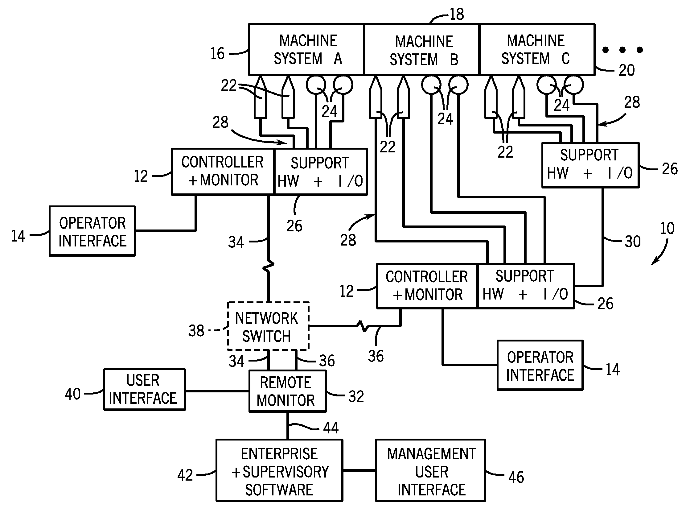
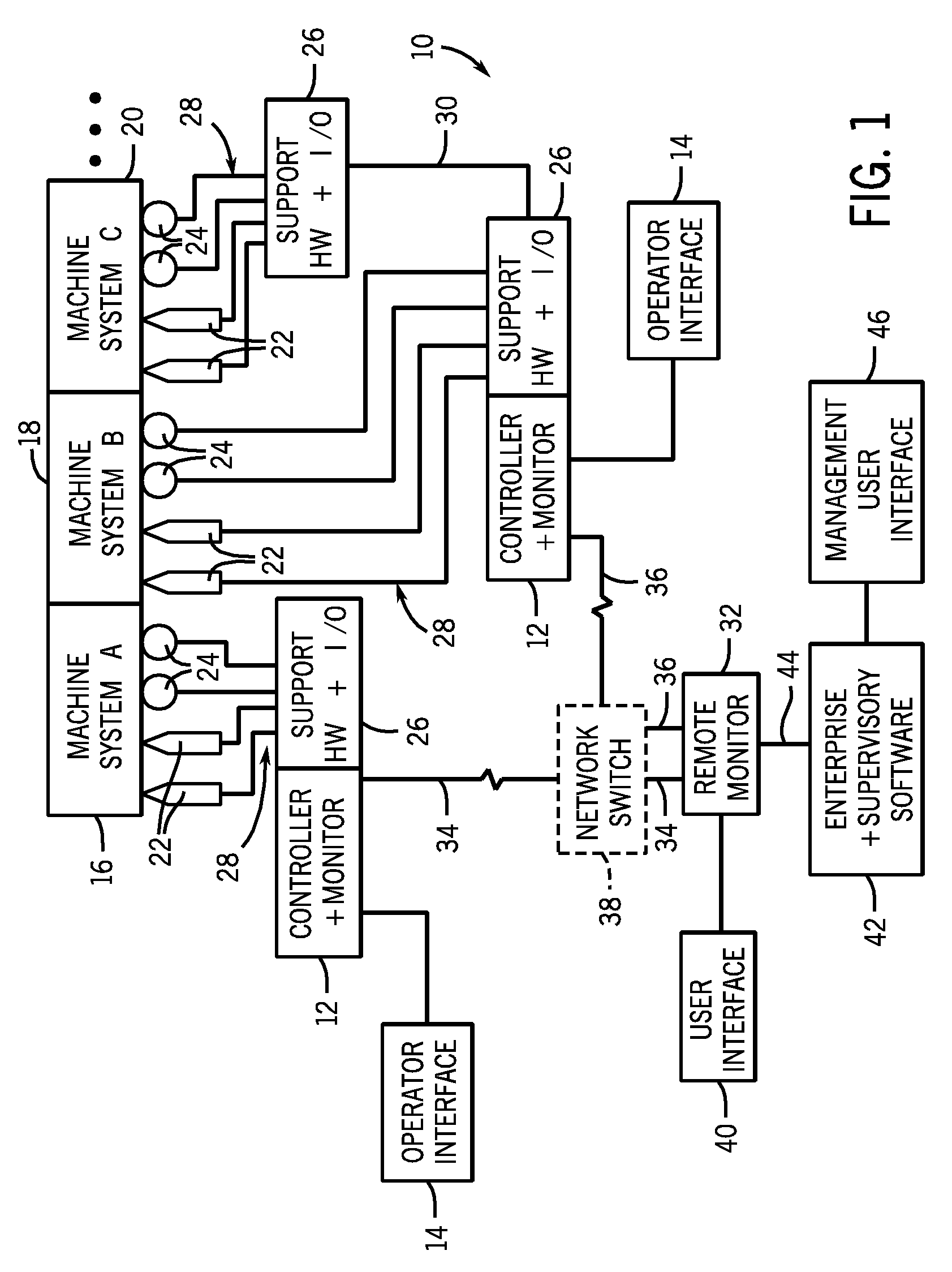
[0015]Turning now to the drawings, and referring first to FIG. 1, a diagrammatical overview of an embodiment of a machine condition monitoring and control system 10 is illustrated. The machine condition monitoring and control system 10 is particularly well suited for monitoring, detecting, and controlling a wide range of dynamic operating parameters of mechanical machine systems. In particular, the system is well suited to various types of rotary equipment, although other applications may be envisaged for certain aspects of the present technique. As referred herein, the term “dynamic operating condition” or the reference to condition monitoring is intended to convey physical conditions or parameters of a mechanical machine system, as opposed, for example, the electrical conditions. The dynamic conditions may include such characteristics as vibration, rotation, speed, temperature, pressure, and so forth.

[0016]The condition monitoring and control system 10 is designed to allow monitor...


PUM


Abstract

A system, in one embodiment, includes a controller configured to receive sensor signals from a machine system and to control operation of the machine system via actuators. The embodiment also includes function blocks stored and operational in the controller and configured to receive machine condition monitoring information and to calculate vibration parameters based upon the machine condition monitoring information. In another embodiment, the system includes a controller that includes computer code configured to control operation of a machine system via actuators based upon sensor signals. Moreover, the embodiment includes computer code configured to perform vibration monitoring of the machine system, including function blocks configured to receive vibration data and to calculate vibration parameters based upon the vibration data.

Description

BACKGROUND[0001]The invention relates generally to the field of systems for monitoring of mechanical machine systems. More particularly, the invention relates to systems and methods for configuring, processing, and presenting machine condition monitoring information.[0002]Various systems and components may be used to monitor and protect industrial equipment and machines. Depending upon the type of mechanical system, the monitoring and protection components may generate various signals representative of dynamic conditions. The signal-generating components may be sensors and transducers positioned on points of interest of the machine systems. The signals are applied to monitoring circuits that are somewhat remote from the points of interest, and are used to analyze the performance of the machine system. Machine systems thus instrumented may include rotary machines, fans / blowers, pumps, assembly lines, production equipment, material handling equipment, power generation equipment, as we...

Claims


Application Information

Patent Timeline
Patent Type & Authority Applications(United States)
IPC IPC(8): G01H17/00G06F19/00
CPCG05B23/0272G05B23/0216
Inventor LAKOMIAK, JASON E.BURROWS, MICHAEL P.HOOD, GREG L.
Owner ROCKWELL AUTOMATION TECH
Why Eureka
Try Eureka