Servo motor for actuating a mandrel while extruding helical teeth

a servo motor and helical tooth technology, applied in the field of cold extrusion of helical tooth, can solve the problems of large die set element, high cost, and high process investment, and achieve the effects of less die opening height, faster cycle time, and reduced cos

Inactive Publication Date: 2010-04-08
FORD MOTOR CO
View PDF10 Cites 6 Cited by
  • Summary
  • Abstract
  • Description
  • Claims
  • Application Information

AI Technical Summary

Benefits of technology

[0011]The servo motor and controller provides several advantages specific to the process of extruding helical gears including smaller size requires less die opening height; faster cycle time in extruding each gear, functional flexibility by programming the controller to control gear extrusion with many different helical gears and helix angles; fast die changing between different products, sensors for monitoring the extrusion process; and reduced the cost of the extrusion tooling and the hydraulic press.
[0012]The servo motor can be programmed to assist in the extrusion process by generating rotational torques while the hydraulic press actuates in the downward direction permitting better control of forces required to produce precision formed gear tooth profiles.
[0014]The servo controls are linked to a computer which controls axial movement and radial forces of the mandrel, thereby coordinating the press actuation sequence with the rotation and eliminating need for the mechanical lead guide.

Problems solved by technology

Broaching is a costly process, which requires a significant investment in dedicated machinery, lead bar, cutting tools and cutting oils.
Even so, this process also requires an investment in expensive machinery and cutting tools.
The lead guide is an expensive, large element of the die set and must be machined to precise dimensions.
The lead mechanism requires a significant portion of the vertical dimension of the die set, and increases the total size of the hydraulic press.

Method used


Image

  • Servo motor for actuating a mandrel while extruding helical teeth
  • Servo motor for actuating a mandrel while extruding helical teeth
  • Servo motor for actuating a mandrel while extruding helical teeth

Examples


Embodiment Construction

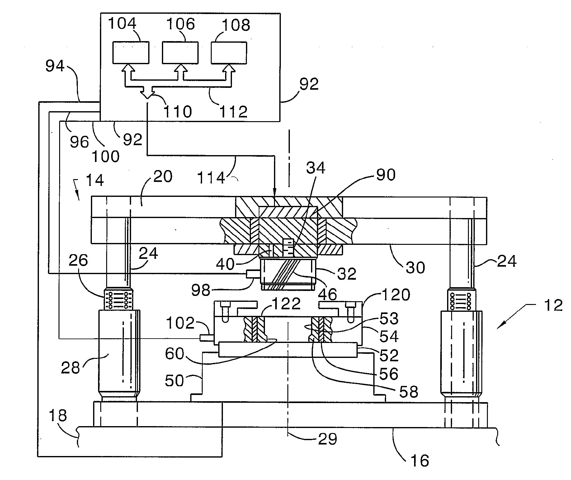
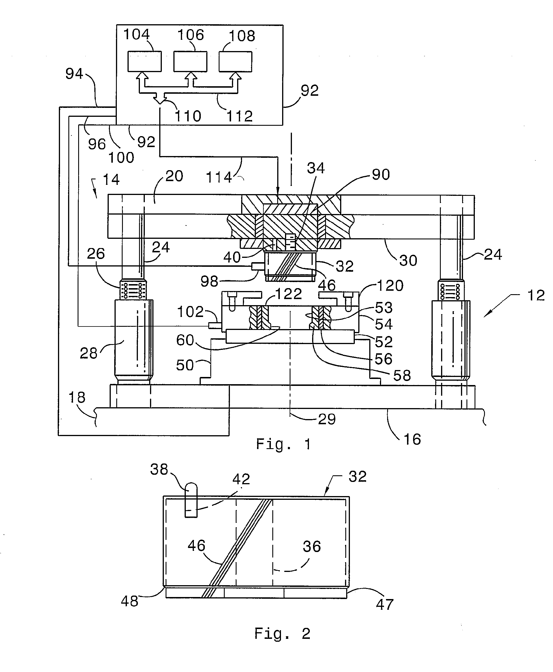
[0020]Referring first to FIGS. 1 and 2, an extrusion die assembly 12, mounted in a hydraulic press 14, includes a lower die plate 16, resting on a base portion 18 of the press 14, and an upper die plate 20. Die guide posts 24 extend between upper die plate 20 and lower die plate 16. One end of each die guide post 24 is fixed to upper die plate 20; the opposite end of each die guide post 24 has a ball bearing cage 26 attached to it. Affixed to lower die plate 16 are guide bushings 28, with each guide bushing 28 aligned with one ball bearing cage 26. Ball bearing cages 26 telescopically slide into their respective guide bushings 28 to allow axial movement of upper die plate 20 relative to lower die plate 16, minimizing friction and maintaining the two die plates 16, 20 mutually parallel. The assembly 12 is concentric with and translates along an axis 29.

[0021]A support plate 30, guided on the guide posts 24, is secured to the upper die plate 20 for movement with plate 20 along axis 29...


PUM

PropertyMeasurementUnit
helix angleaaaaaaaaaa
dimensionsaaaaaaaaaa
volumeaaaaaaaaaa

Abstract

An apparatus for extruding helical teeth in a gear blank includes a press including a die plate and a die base, the die plate being movable along an axis relative to the die base, the die base supporting the gear blank. A mandrel, aligned with the axis and moveable with the die plate along the axis, includes a surface that includes helical die teeth. A servo motor drives the mandrel in rotation about the axis to the required helix angle as the mandrel moves axially relative to the gear blank.

Description

BACKGROUND OF THE INVENTION[0001]1. Field of the Invention[0002]This invention relates generally to forming spline teeth or gear teeth, and more particularly to cold extruding helical teeth in a gear blank workpiece.[0003]2. Description of the Prior Art[0004]Planetary gear units of the type used in automotive transmissions include ring gears having internal helical teeth rather than straight gears even though helical gear teeth are more difficult to form. The internal gear teeth must be formed with very precise dimensions and spacing in order to perform correctly.[0005]The helical teeth may be formed by broaching, which is a cutting process in which a large broaching bar with cutting teeth is pulled through a gear blank to form the teeth. Broaching is a costly process, which requires a significant investment in dedicated machinery, lead bar, cutting tools and cutting oils. Broaching can only be applied to parts accessible in both axial directions since the long broach bar must be pu...

Claims


Application Information

Patent Timeline
Patent Type & Authority Applications(United States)
IPC IPC(8): B21K1/30B21C23/18F16H55/00
CPCB21C23/14B21K1/30F16H55/17Y10T29/49476Y10T29/49474Y10T408/08Y10T29/49478Y10T74/19986
Inventor SZUBA, JOSEPH A.TONELLO, EMILO A.COOK, MICHAEL A.WHITBECK, RODNEY G.
Owner FORD MOTOR CO
Why Eureka
Try Eureka