Bi-modal bleed valve assembly for gas turbine engine

a gas turbine engine and bleed valve technology, applied in the direction of machines/engines, process and machine control, instruments, etc., can solve the problems of unnecessary weight, cost, complexity, and use of servo-controlled bleed valve assemblies and their associated hardwar

Inactive Publication Date: 2010-04-08
HONEYWELL INT INC
View PDF6 Cites 37 Cited by
  • Summary
  • Abstract
  • Description
  • Claims
  • Application Information

AI Technical Summary

Benefits of technology

[0006]A bi-modal bleed valve assembly is provided. In one embodiment, the bi-modal bleed valve assembly includes a housing assembly having a bleed inlet, a bleed outlet, a control servo port, and a control chamber therein. A main flow control valve is fluidly coupled to the control chamber and configured to move between an open position and a closed position to regulate fluid flow from the bleed inlet to the bleed outlet. The main flow control valve is configured to move from an open position to a closed position when the pressure within the control chamber surpasses a predetermined threshold. A switching valve is fluidly coupled between the bleed inlet, the servo control port, and the control chamber. The switching valve is configured to route fluid flow into the control chamber from: (i) the bleed inlet in an autonomous mode, and (ii) the servo control port in a servo-controlled mode.

Problems solved by technology

In this latter group of GTE platforms, the utilization of a servo-controlled bleed valve assembly and its associated hardware (e.g., servo control valve, plumbing, etc.) adds unnecessary weight, cost, and complexity to the gas turbine engine.

Method used


Image

  • Bi-modal bleed valve assembly for gas turbine engine
  • Bi-modal bleed valve assembly for gas turbine engine
  • Bi-modal bleed valve assembly for gas turbine engine

Examples


Embodiment Construction

[0012]The following Detailed Description is merely exemplary in nature and is not intended to limit the invention or the application and uses of the invention. Furthermore, there is no intention to be bound by any theory presented in the preceding Background or the following Detailed Description.

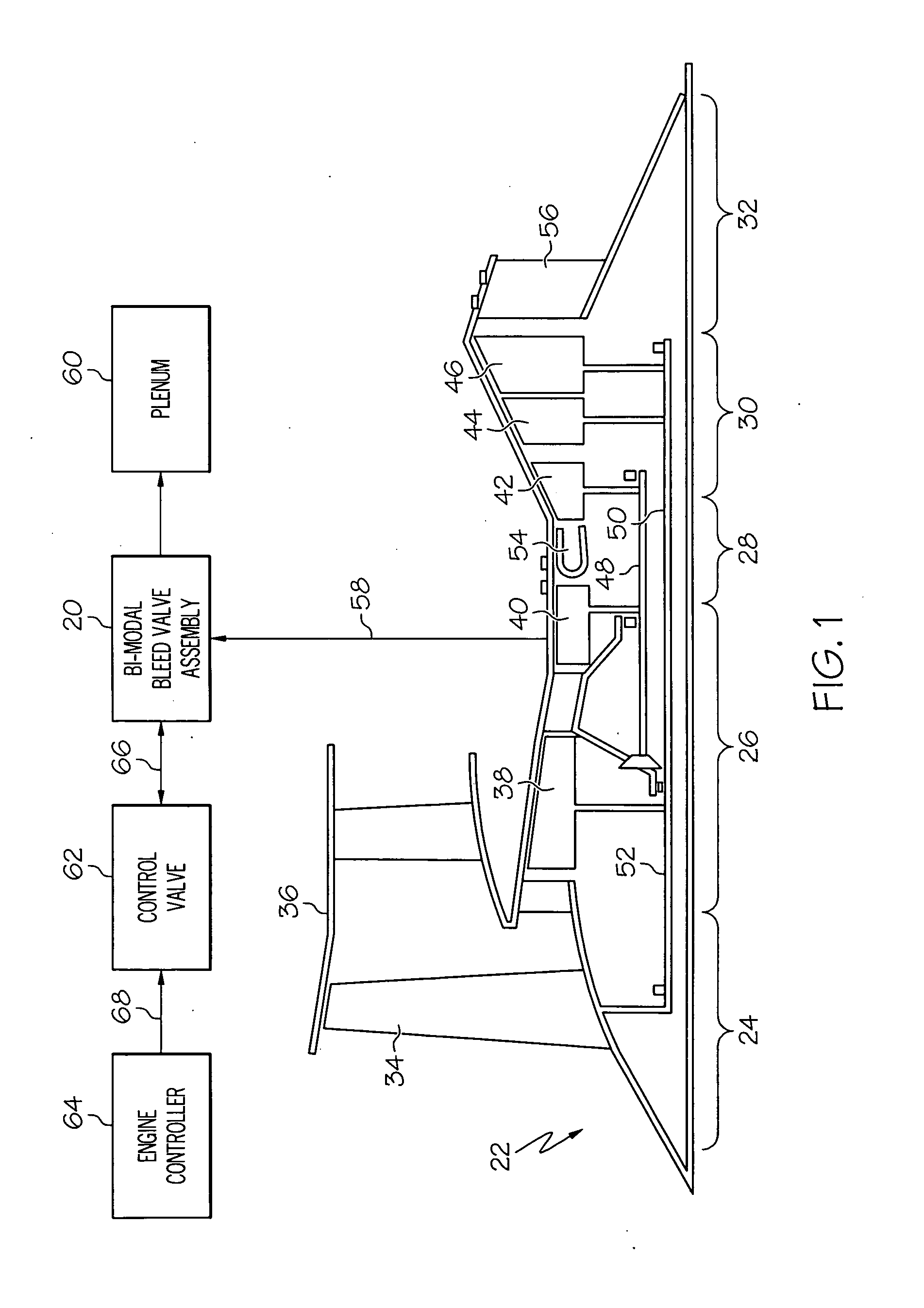
[0013]FIG. 1 is a functional schematic of a bi-modal bleed valve assembly 20 in accordance with an exemplary embodiment of the present invention. Bi-modal bleed valve assembly 20 is especially well suited for regulating the air pressure within the compressor of a gas turbine engine of the type commonly deployed on an aircraft. For this reason, bi-modal bleed valve assembly 20 is illustrated in FIG. 1 and described below in conjunction with an exemplary gas turbine engine (GTE) 22. This example notwithstanding, it will be appreciated that embodiments of the bi-modal bleed valve assembly may be utilized in alternative types of applications to regulate the pressure of various other fluids.

[0014...


PUM


Abstract

A bi-modal bleed valve assembly is provided. In one embodiment, the bi-modal bleed valve assembly includes a housing assembly having a bleed inlet, a bleed outlet, a control servo port, and a control chamber therein. A main flow control valve is fluidly coupled to the control chamber and configured to move between an open position and a closed position to regulate fluid flow from the bleed inlet to the bleed outlet. The main flow control valve is configured to move from an open position to a closed position when the pressure within the control chamber surpasses a predetermined threshold. A switching valve is fluidly coupled between the bleed inlet, the servo control port, and the control chamber. The switching valve is configured to route fluid flow into the control chamber from: (i) the bleed inlet in an autonomous mode, and (ii) the servo control port in a servo-controlled mode.

Description

TECHNICAL FIELD[0001]The present invention relates generally to pressure regulating systems and, more particularly, to a bi-modal bleed valve assembly suitable for regulating the air pressure within the compressor of a gas turbine engine of the type commonly deployed on an aircraft.BACKGROUND[0002]The compressor section of a gas turbine engine (GTE) may include one or more turbines, which may each include multiple bladed discs dividing the compressor section into a number of compressor stages. The compressor section of a three spool turbofan jet engine, for example, may include an intermediate turbine and a high pressure turbine disposed in axial flow series. The intermediate pressure turbine is supported by a first spool, which is rotatably mounted within the GTE housing. Similarly, the high pressure turbine is supported by a second spool, which is rotatably mounted within the GTE housing and which extends through a longitudinal channel provided through the first spool. During oper...

Claims


Application Information

Patent Timeline
Patent Type & Authority Applications(United States)
IPC IPC(8): F02C9/18F16K31/124
CPCF01D17/105F05D2270/101G05D7/014F02C9/18F04D27/0215F04D27/023Y10T137/7758Y10T137/7762Y10T137/7768Y10T137/7782
Inventor FRANCONI, ROBERT B.
Owner HONEYWELL INT INC
Why Eureka
Try Eureka