Eureka AIR delivers breakthrough ideas for toughest innovation challenges, trusted by R&D personnel around the world.

Dispenser arrangement for fluidic dispensing control in microfluidic system

Inactive Publication Date: 2010-04-08
AGENCY FOR SCI TECH & RES
View PDF6 Cites 6 Cited by
  • Summary
  • Abstract
  • Description
  • Claims
  • Application Information

AI Technical Summary

Benefits of technology

[0020]In another embodiment of the invention, the covering layer is situated above the hollow portion and comprises a reinforced portion arranged such that it is in contact with the first end of the hollow portion when a force is exerted on the covering layer. The reinforced portion can be of the same material as the covering layer but may be thicker in dimensions. Alternatively, the reinforced portion can comprise a different material from the covering layer, usually the material for the reinforced portion is thicker in dimension or has a higher tensile strength and therefore is mechanically more resistant to stress. The reinforced portion prevents the covering layer from tearing when a force is exerted onto the covering layer towards the valve. Some examples of materials for the reinforced portion could be polymethyl methacrylate (PMMA), COC or PC but are not so limited.

Problems solved by technology

Controlling the dispensing of fluid and fluid flow rate in prior art devices to prevent back flow and cross mixing of fluids is difficult.
It is also tough to maintain a low dead volume in the prior art devices.
These difficulties in controlling the dispensing of fluid may lead to contamination of different fluids in microfluidic systems.

Method used


Image

  • Dispenser arrangement for fluidic dispensing control in microfluidic system
  • Dispenser arrangement for fluidic dispensing control in microfluidic system
  • Dispenser arrangement for fluidic dispensing control in microfluidic system

Examples


Embodiment Construction

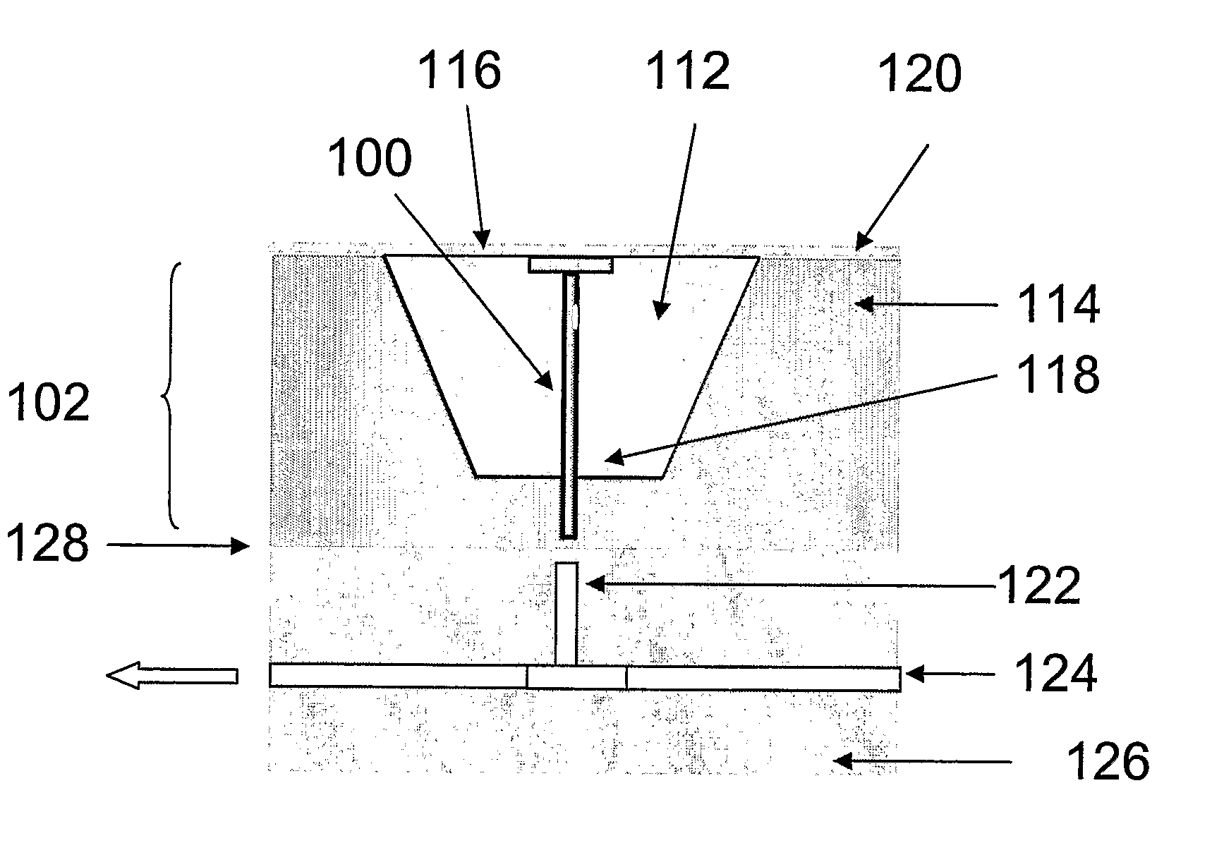
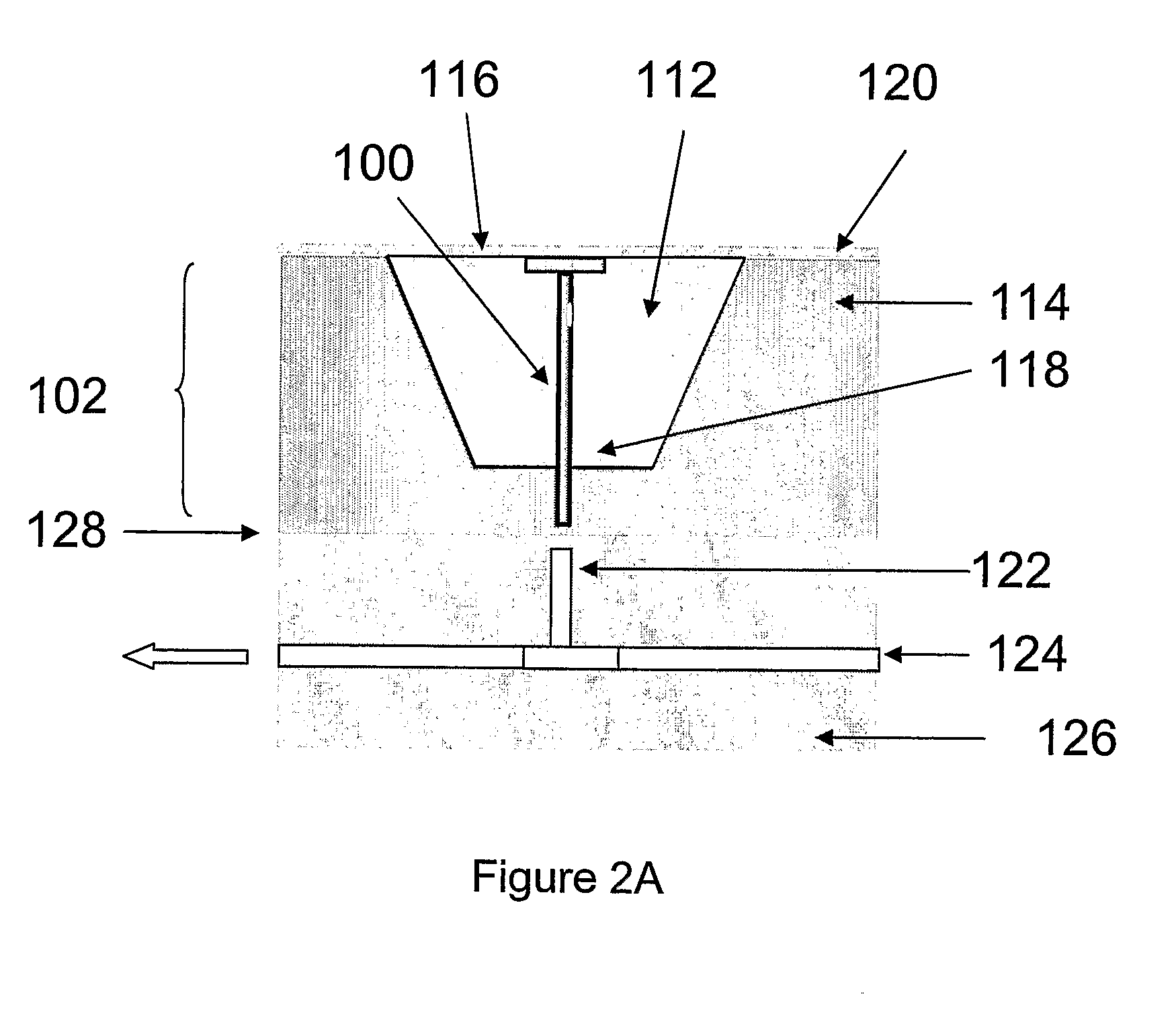
[0051]Exemplary embodiments of a dispenser arrangement for fluidic dispensing control into a microfluidic component such as a channel are described in detail below with reference to the accompanying figures. In addition, the exemplary embodiments described below can be modified in various aspects without changing the essence of the invention.

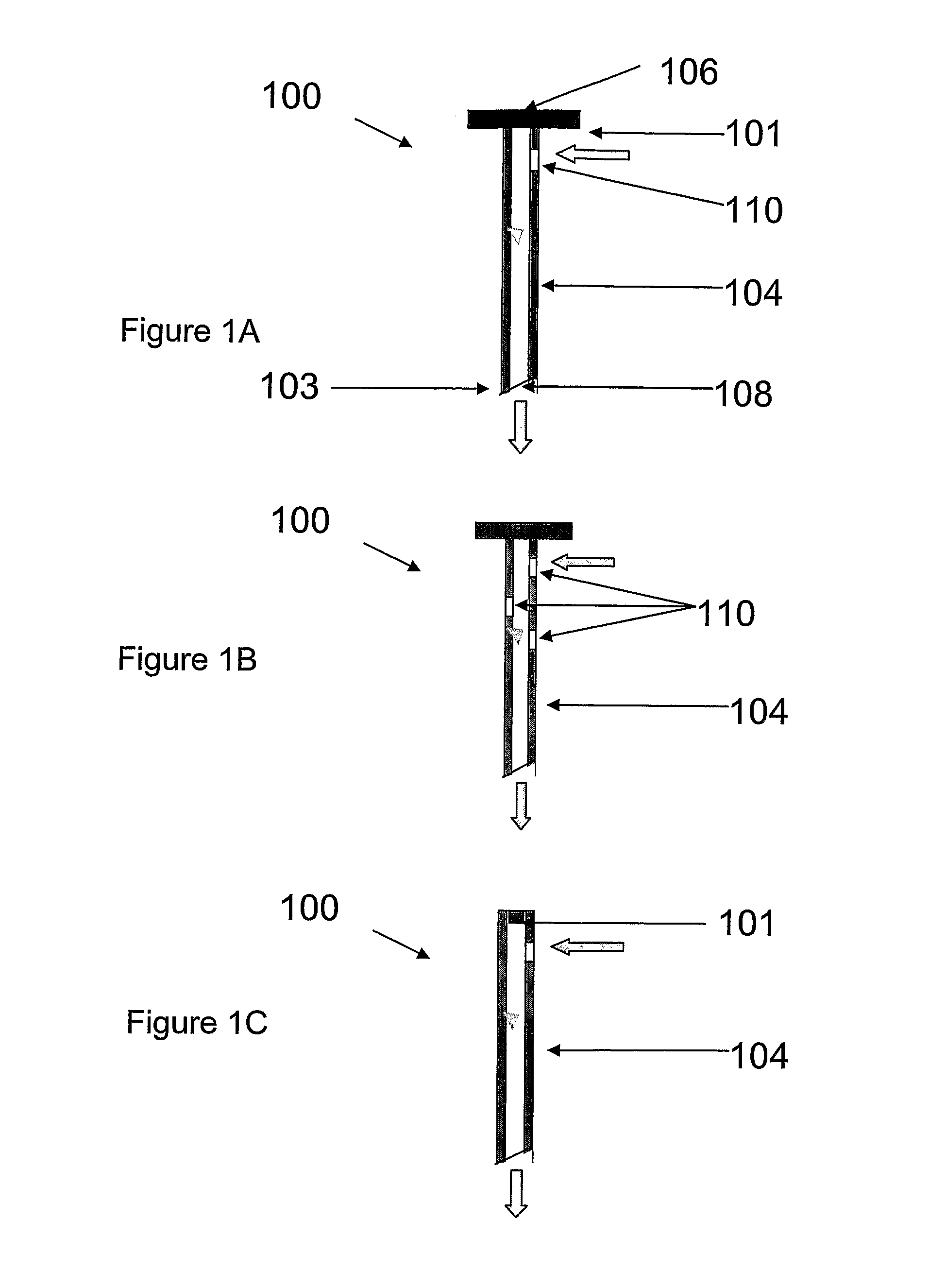
[0052]FIG. 1A shows a cross-sectional view of a valve according to an embodiment of the present invention. The valve has been referred to as the pin valve for illustrative purposes. The pin valve 100 comprises an elongated hollow portion or shaft 104 having a body and two ends 101, 103. A sealing portion or sealing cap 106 is positioned at an end 101 of the hollow portion 104 and the other end 103 of the hollow portion 104 is an opening with a slant tip 108. Another opening 110 is present on the body of the hollow portion 104, nearer to the sealing cap 106, but not limited to this position. The position of the opening 110 on the body of the holl...


PUM


Abstract

A dispenser arrangement for fluidic dispensing control into a microfluidic component comprising an enclosed fluid holding area having a base portion and a top portion and a valve adapted to be movable between an open position and a closed position and positioned at least partially in the fluid holding area. The valve comprises an elongated hollow portion having a body and two ends adapted for fluid flow from the fluid holding area to the microfluidic component in the open position, a first opening on the body of the hollow portion positioned within the fluid holding area allowing fluid communication from the fluid holding area to the microfluidic component in the open position, a sealing portion connected to a first end of the hollow portion positioned within the fluid holding area adapted for sealing connection with the top portion of the fluid holding area in the closed position and a slant second opening at a second end of the hollow portion positioned outside of the fluid holding area. The slant second opening is adapted to pierce through a sealing layer covering the microfluidic component in the open position and to insert into a first substrate housing the microfluidic component in the closed position. A dispenser unit comprising a dispenser arrangement and an actuator, wherein the actuator is a piston is also disclosed.

Description

CROSS-REFERENCE TO RELATED APPLICATIONS[0001]This application is a National Stage Application under 35 USC §371(c) of PCT Application No. PCT / SG2006 / 000276, entitled “A DISPENSER ARRANGEMENT FOR FLUIDIC DISPENSING CONTROL IN MICROFLUDIC SYSTEM,” filed Sep. 19, 2006, which is hereby incorporated by reference herein.FIELD OF THE INVENTION[0002]The present invention relates to the field of microfluidic systems, and in particular, to a dispenser arrangement for fluidic dispensing control into a microfluidic component such as channel, mixer, valve, pump, reservoir but not so limited in a microfluidic system.BACKGROUND OF THE INVENTION[0003]Microfluidic systems such as microfluidic devices, cartridges, packages, lab-on-a-chip (LOC) and micro total analysis system (micro-TAS) for example require fluidic dispensing control to realize particular protocol. Fluidic dispensing control includes controlling of the fluids' flow sequence, flow duration, flow direction and flow rate. A microfluidic ...

Claims


Application Information

Patent Timeline
IPC IPC(8): F15C1/00B67D7/06F15C1/04
CPCF15C5/00Y10T137/2213Y10T137/218Y10T137/2224Y10T137/2218
Inventor XIE, LINGPREMACHANDRAN, CHIRAYARIKATHUVEEDU SANKARAPILLAICHONG, SER CHOONG
Owner AGENCY FOR SCI TECH & RES
Why Eureka
Eureka Blog
Learn More