
Heat exchanger and method of operating the same

a technology of heat exchanger and fluid, which is applied in the direction of indirect heat exchangers, laminated elements, lighting and heating apparatus, etc., can solve the problems of difficult to achieve a uniform distribution of fluid over multiple parallel passages, and the heat exchanger performance tends to suffer

Active Publication Date: 2010-04-08
MODINE MFG CO
View PDF22 Cites 82 Cited by
  • Summary
  • Abstract
  • Description
  • Claims
  • Application Information

AI Technical Summary

Benefits of technology

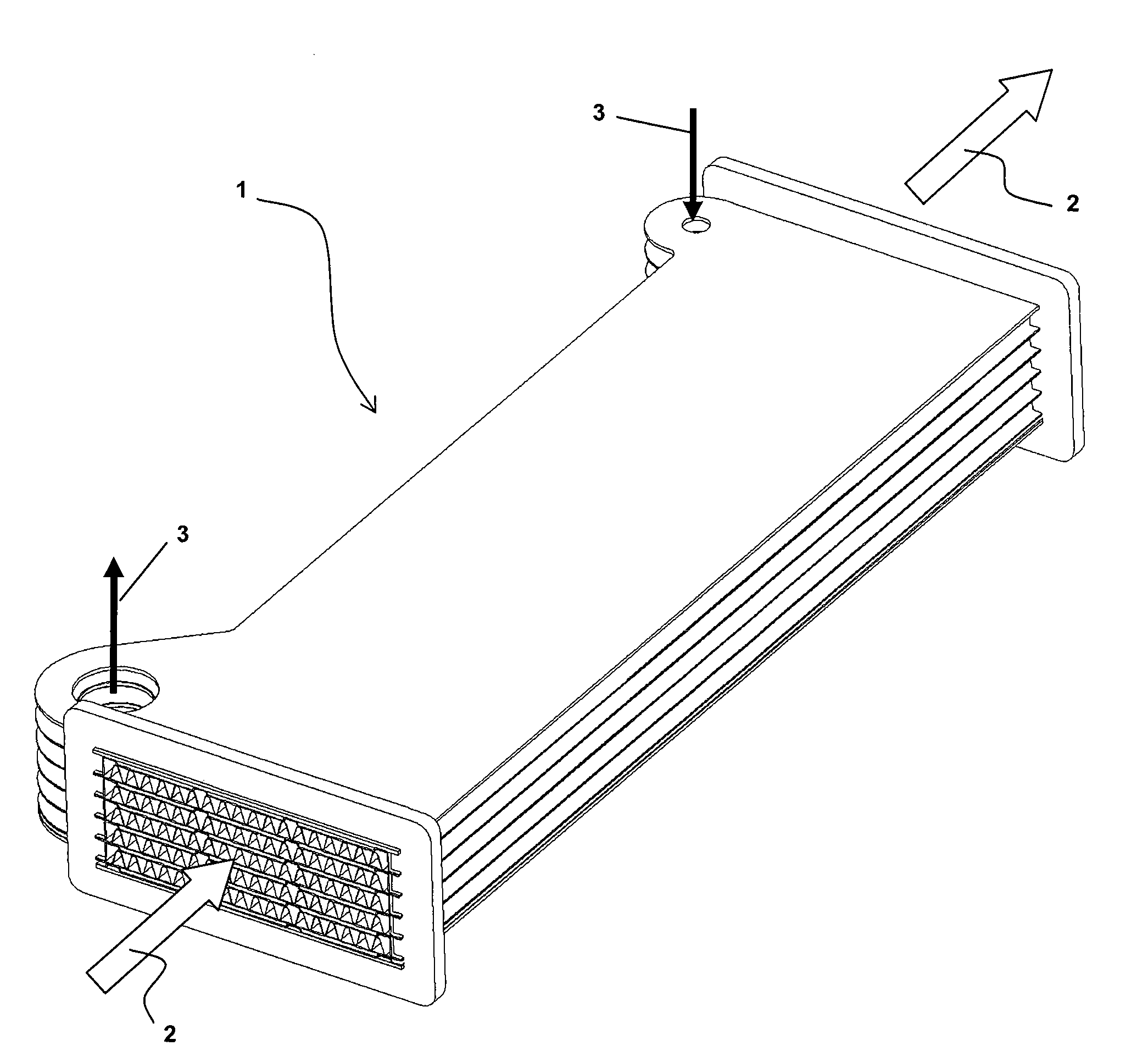
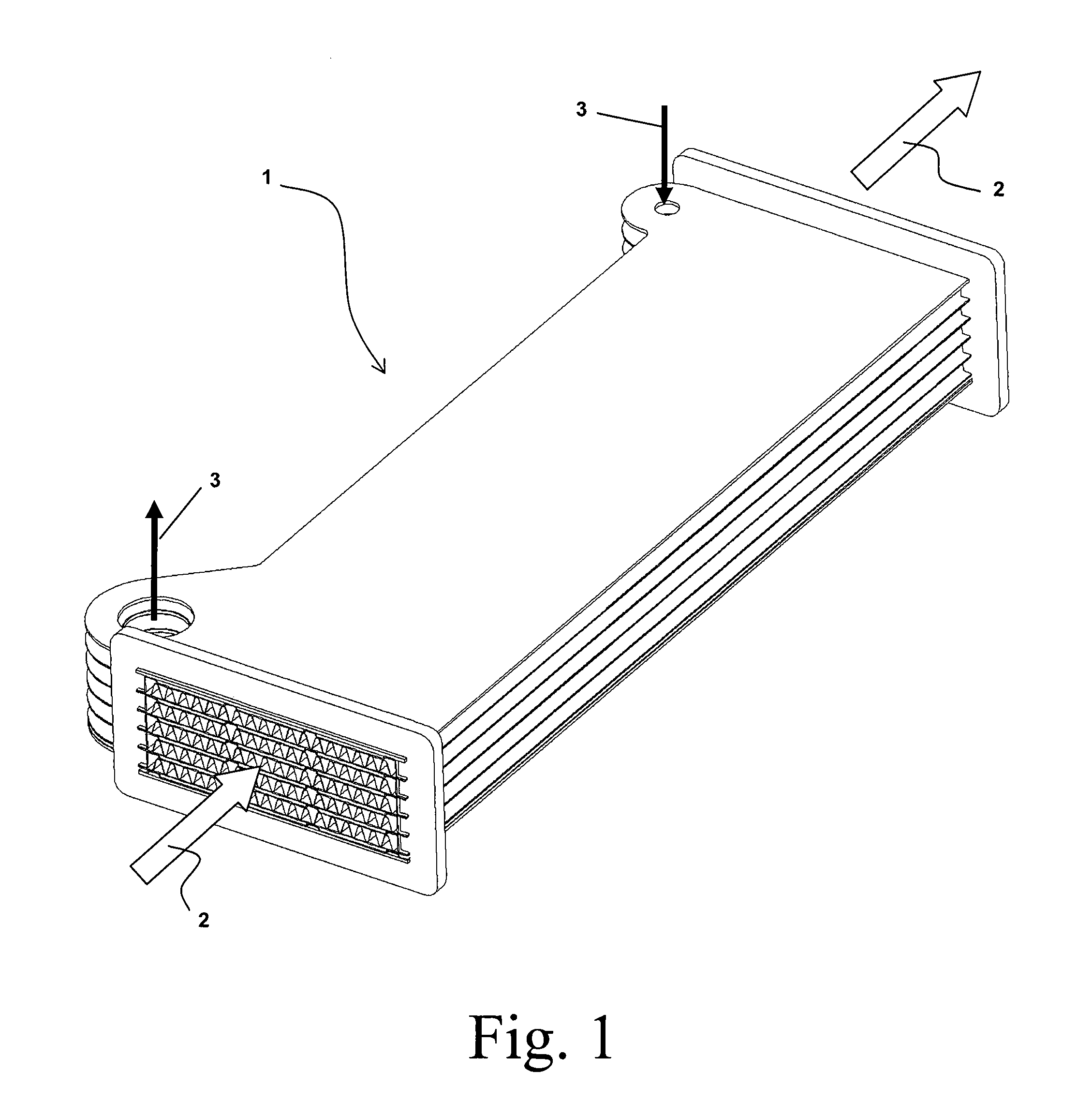
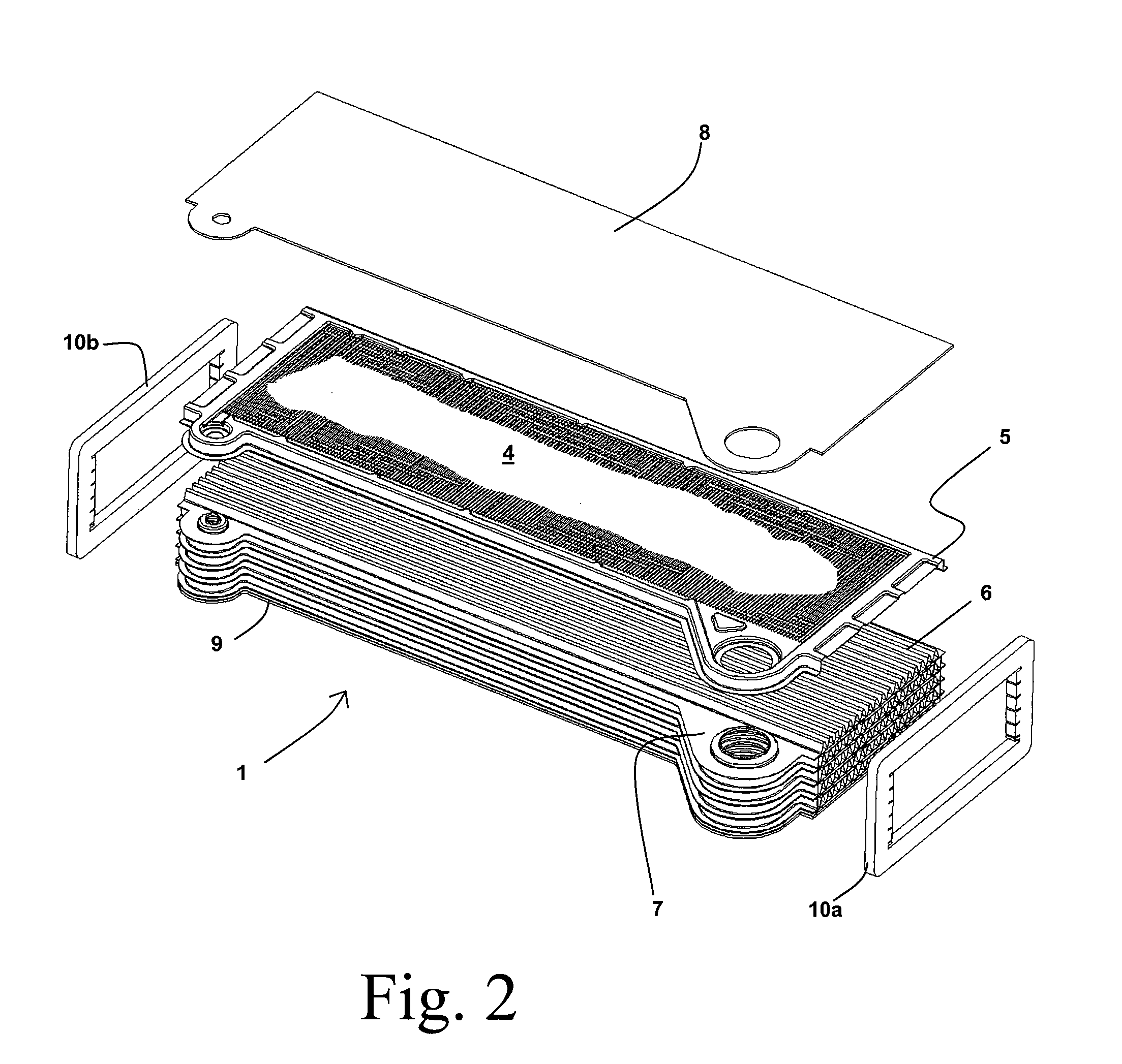
[0008]In some embodiments, the pressure resistance and heat transfer performance of the heat exchanger may be improved by having a uniformly narrow channel width for the flow channels of the fluid flow plates. In some embodiments the second collection manifold can consist of one or more slots extending through the fluid flow plate. In some embodiments the one or more slots can each have a slot width that is approximately equal to the channel width.

Problems solved by technology

Attempts to use stacked plate style heat exchangers in applications where one of the fluids experiences a change of phase from a liquid to a vapor have been problematic.
The vapor fraction tends to separate from the liquid fraction due to the substantial differences in densities between the phases, making it difficult to achieve a uniform distribution of the fluid over the multiple parallel passages.
When the distribution is not uniform, the performance of the heat exchanger tends to suffer.
Separation of the phases of the evaporating fluid can result in liquid flooding of certain regions, with slugs of the liquid forced through the heat exchanger at a non-constant rate.
A disadvantage of using a tube and fin evaporator construction in such applications is the difficulties that it poses in arranging the hot and cold fluid flows in a circuiting arrangement other than cross-flow.

Method used


Image

  • Heat exchanger and method of operating the same
  • Heat exchanger and method of operating the same
  • Heat exchanger and method of operating the same

Examples


Embodiment Construction

[0020]Before any embodiments of the invention are explained in detail, it is to be understood that the invention is not limited in its application to the details of construction and the arrangement of components set forth in the following description or illustrated in the following drawings. The invention is capable of other embodiments and of being practiced or of being carried out in various ways. Also, it is to be understood that the phraseology and terminology used herein is for the purpose of description and should not be regarded as limiting. The use of “including,”“comprising,” or “having” and variations thereof herein is meant to encompass the items listed thereafter and equivalents thereof as well as additional items. Unless specified or limited otherwise, the terms “mounted,”“connected,”“supported,” and “coupled” and variations thereof are used broadly and encompass both direct and indirect mountings, connections, supports, and couplings. Further, “connected” and “coupled”...


PUM


Abstract

An evaporative heat exchanger including a plurality of parallel flow passages extending through the heat exchanger and together defining a first fluid flow path, and a plurality of substantially parallel stacked plates interleaved with the parallel flow passages. Each plate can have first, second, and third sets of flow channels, a first collection manifold adjacent to an end of the plate and connecting the first and second passes, and a second collection manifold. The second collection manifold can intersect the second set of flow channels and at least some of the third set of flow channels. The plate separates the first set of flow channels from the second collection manifold.

Description

CROSS-REFERENCE TO RELATED APPLICATIONS[0001]The present application claims priority to U.S. Provisional Patent Application Ser. No. 61 / 102,458, filed Oct. 3, 2008, the entire contents of which is hereby incorporated by reference.FIELD OF THE INVENTION[0002]The present invention relates to heat exchangers, and more particularly to evaporative heat exchangers having a number of stacked plates at least partially defining two separate and substantially adjacent fluid flow pathsSUMMARY OF THE INVENTION[0003]Attempts to use stacked plate style heat exchangers in applications where one of the fluids experiences a change of phase from a liquid to a vapor have been problematic. In such applications the fluid that is evaporating exists, over at least a portion of its flow path through the heat exchanger, as a two-phase fluid having both vapor and liquid fractions. The vapor fraction tends to separate from the liquid fraction due to the substantial differences in densities between the phases,...

Claims


Application Information

Patent Timeline
Patent Type & Authority Applications(United States)
IPC IPC(8): F28F13/00F28F3/08
CPCF22B27/00F28D9/0068F28D9/0075F28F9/026F28D2021/0071F28F3/025F28D2021/0064
Inventor YIN, JIAN-MINHUGHES, GREGORY G.
Owner MODINE MFG CO
Learn More