
Glazed Roof of a Motor Vehicle, Corresponding Method of Assembly and Corresponding Vehicle

Inactive Publication Date: 2010-04-08
WAGON SAS
View PDF9 Cites 9 Cited by
  • Summary
  • Abstract
  • Description
  • Claims
  • Application Information

AI Technical Summary

Benefits of technology

[0023]Thus, a roof is obtained which is simple to produce and to mount, offering a good quality of opening and being able to be varied to offer a wide range of functionalities, shapes and appearances (for example offering one or more openings of a size being able to be adjusted simply, . . . ). Moreover, the roof which is thus implemented meets the current requirements and expectations in particular in terms of aesthetic quality, due to the flush appearance of the roof, security with respect to glass breakages due to the presence of the retaining element, aerodynamic qualities, ease of mounting and, for certain models of vehicle, of weight of the roof.
[0107]Thus, the mounting of the roof on the chassis is simplified, eliminating the securing operation of the retaining element with the chassis.

Problems solved by technology

This technique presents the disadvantage of only allowing a partial freeing of the opening coinciding with the surface of the pane when the latter is reclosed.
A disadvantage of this technique is that the dimensions of the openings in the roof, and consecutively of the glazed surfaces allowing them to be covered, are limited.
However, this technique presents numerous disadvantages.
Moreover, from the aesthetic point of view, this technique does not allow a smooth appearance to be obtained, viewed from the exterior, flush with the body, in the presence of a guide frame of the movable pane.
Furthermore, the means for guiding, actuating and entraining of the movable pane are heavy, cumbersome and complicated to mount.
In addition, they have a high manufacturing cost and conventionally pose problems with regard to tightness.
Mounting on the vehicle, and maintenance, are equally complex.
Furthermore, they impose constraints from the point of view of ergonomics.

Method used


Image

  • Glazed Roof of a Motor Vehicle, Corresponding Method of Assembly and Corresponding Vehicle
  • Glazed Roof of a Motor Vehicle, Corresponding Method of Assembly and Corresponding Vehicle
  • Glazed Roof of a Motor Vehicle, Corresponding Method of Assembly and Corresponding Vehicle

Examples


Embodiment Construction

[0121]As already indicated, the general principle of an embodiment of the invention rests in particular on a novel approach of the realization of a glazed roof for a motor vehicle, in which an opening can be released, and which offers a flush appearance with a chassis element of the body viewed from the exterior of the vehicle.

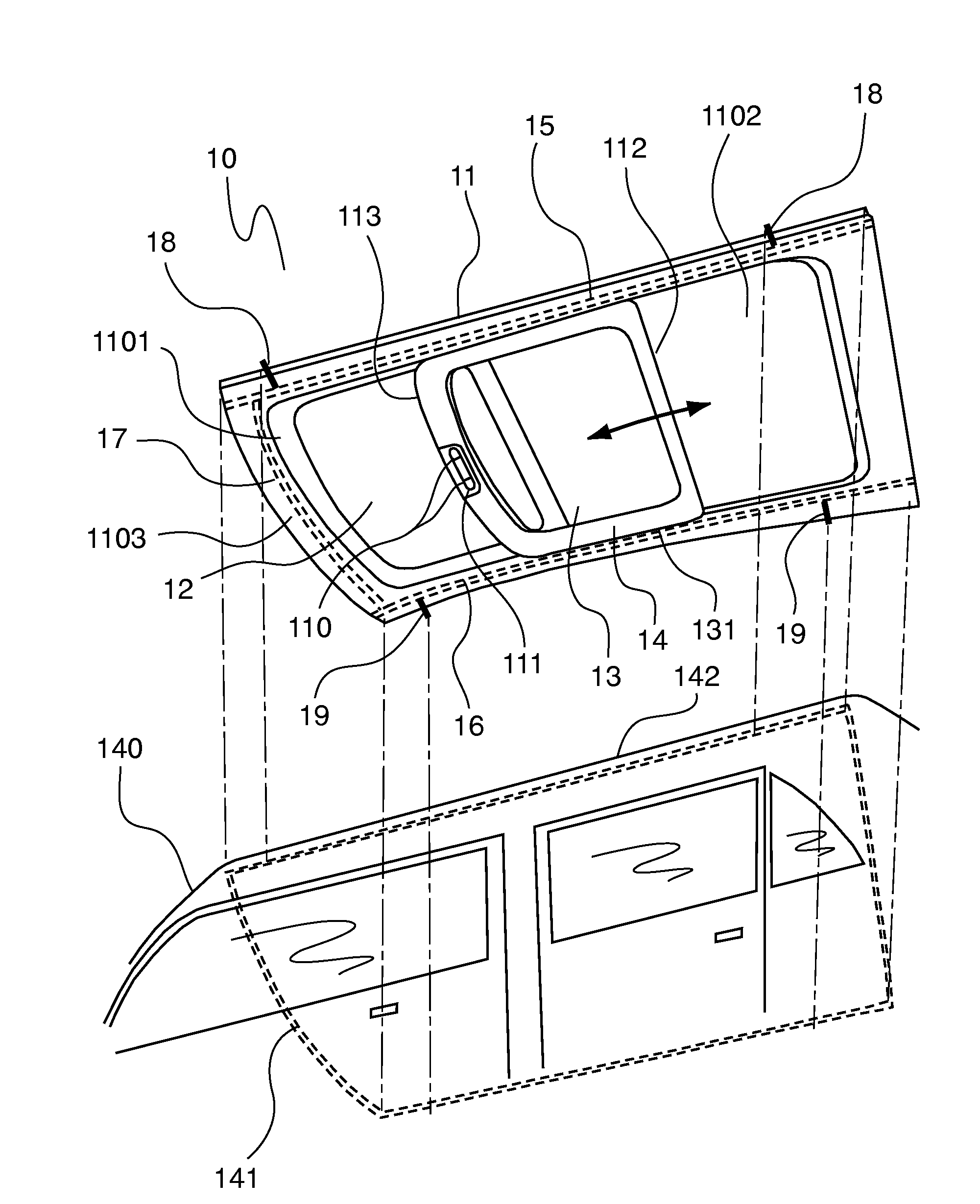
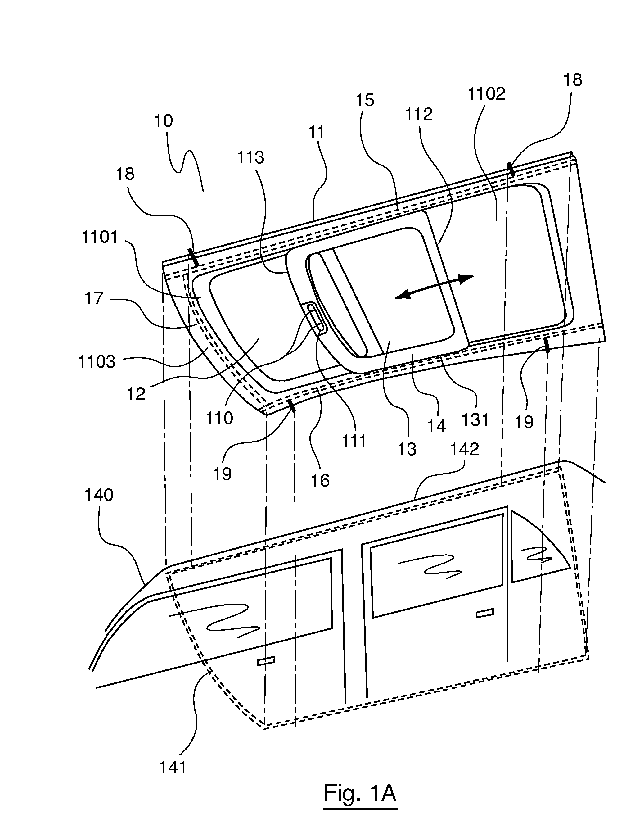
[0122]FIG. 1A illustrates, in a perspective view, a particular embodiment of the invention in which the roof 10 (hereinafter designated “flush roof”) comprises a fixed glazed structure 11, pierced by an opening 12, and a movable sliding element 131 (shown in partial opening position) with respect to this fixed structure.

[0123]The glazed structure 11, for example made of hardened glass and advantageously curved to give the roof a shape meeting the current criteria in terms of design, comfort or penetration in the air . . . presents an exterior contour which coincides substantially with an receiving surround 141 on the chassis 140 of the vehicle and is secured b...


PUM


Abstract

A glazed roof of a motor vehicle is provided, which includes at least one opening and a fixed glazed structure bearing at least one element sliding on the inside of the vehicle and intended to close the opening(s). The glazed structure has an external contour coinciding with an accommodating surround on the chassis of the vehicle so the contour can be secured to the accommodating surround, as a flush fit. Each of the sliding elements is guided along two rails secured to the surface of the fixed structure, in a region distant from the external contour so as not to interfere with the securing of the latter to the accommodating surround. The roof has at least one retaining element, having a first end secured to one of the rails and a second end secured to the chassis. Each of the retaining elements is positioned at right angles to the rail.

Description

CROSS-REFERENCE TO RELATED APPLICATIONS[0001]This Application is a Section 371 National Stage Application of International Application No. PCT / EP2007 / 063483, filed Dec. 6, 2007 and published as WO2008 / 068325 on Jun. 12, 2008, not in English.STATEMENT REGARDING FEDERALLY SPONSORED RESEARCH OR DEVELOPMENT[0002]None.THE NAMES OF PARTIES TO A JOINT RESEARCH AGREEMENT[0003]None.FIELD OF THE DISCLOSURE[0004]The field of the disclosure is that of roofs of motor vehicles. More precisely, the disclosure concerns glazed roofs comprising at least one opening cooperating with a movable sliding glazed panel.[0005]In the present patent application, sliding means the case where the glazed panel remains permanently parallel to a reference plane (decomposition of its displacement in two rectilinear movements) as well as where it has a slanting displacement.BACKGROUND OF THE DISCLOSURE[0006]The current tendency in the subject of motor vehicles, whether an automobile, a utility vehicle, a lorry or a b...

Claims


Application Information

Patent Timeline
IPC IPC(8): B60J7/05B60J10/12E05C1/12B60J10/82
CPCB60J7/022B60J1/001Y10T292/0976
Inventor BILLY, DAVIDFOUREL, PASCALSANDRIN, XAVIER
Owner WAGON SAS
Learn More