

Double-guided pressurized fluid distributor
- Summary
- Abstract
- Description
- Claims
- Application Information
AI Technical Summary
Benefits of technology
Problems solved by technology
Method used
Image

Examples
second embodiment
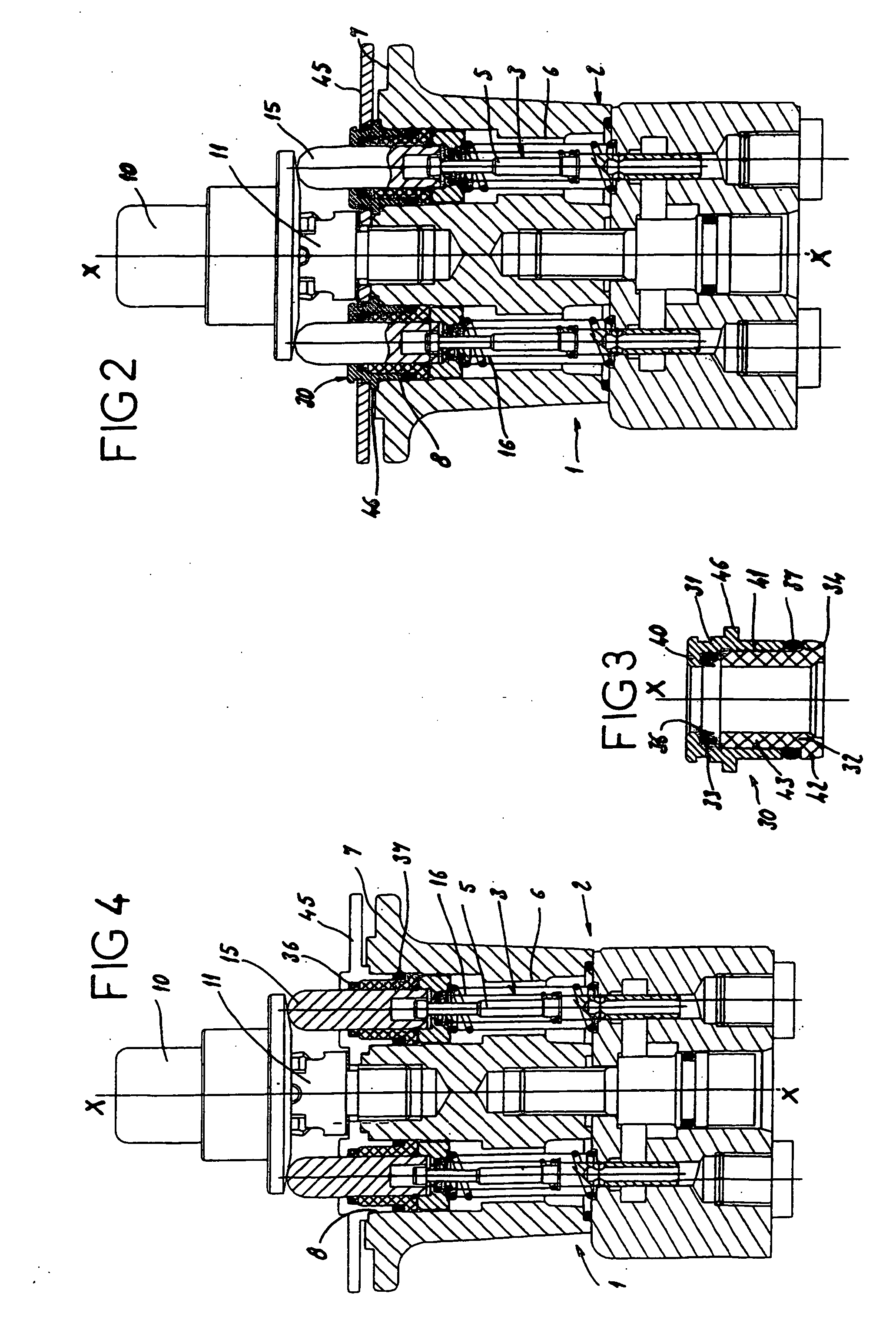
[0046] In the guide 30 shown in FIG. 4, the upper portion 31 of the guide 30 is made of the same material as the flange 45. This minimizes the number of constituent parts providing the guidance of the pushrod 15 because, during the assembly, the upper portion of the guide is fixedly attached to the flange 45. As previously, the outer seal 37 is placed against the shoulder of the lower portion 32 of the guide 30 while the inner seal 36 is placed inside the shoulder supported by the retention flange 45, the lower portion 32 then being nested into the flange 45.
third embodiment
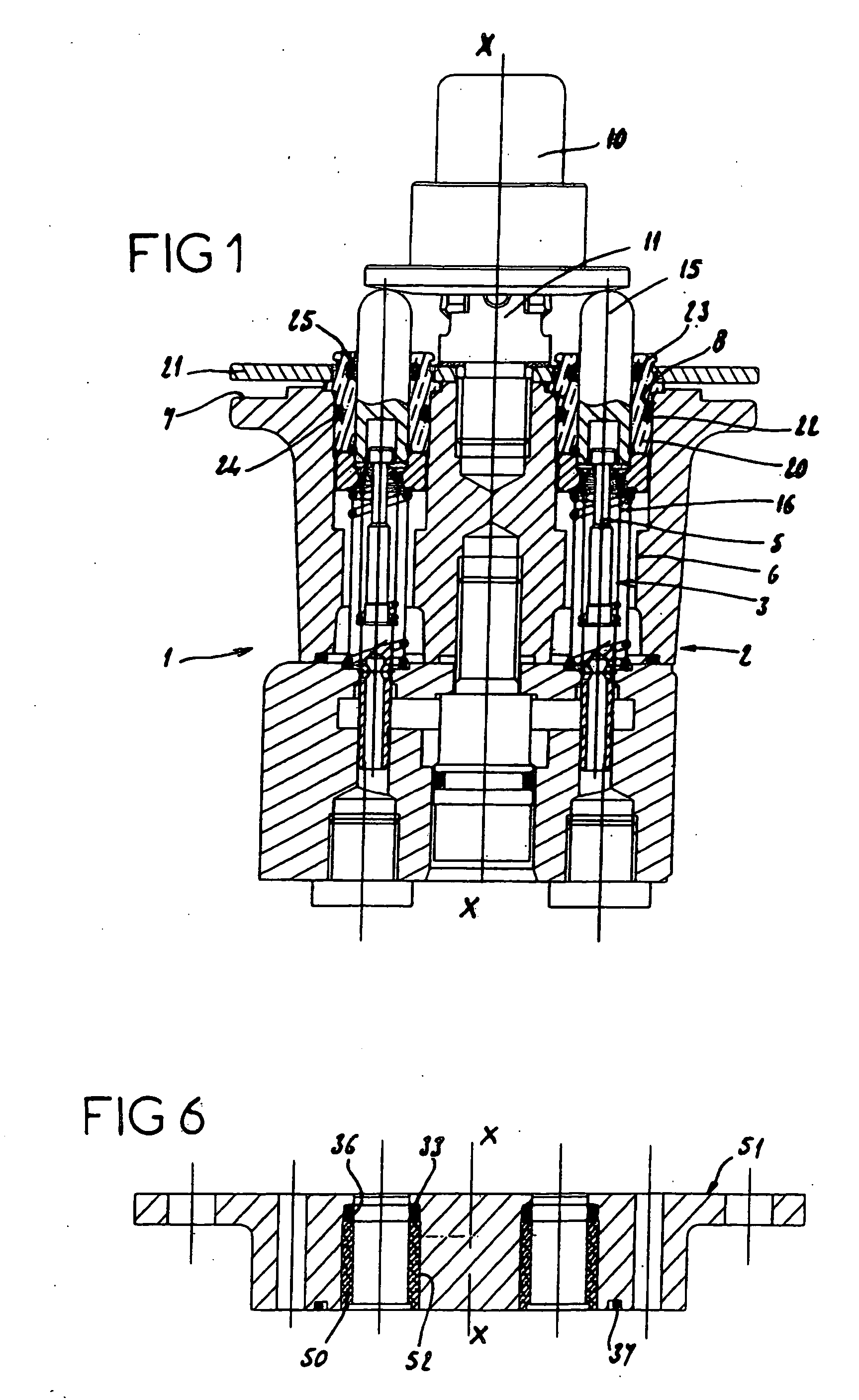
[0047] In the guide shown in FIGS. 5 and 6, the guide 30 consists of a single portion 50 of generally cylindrical shape. The retention flange 51 is much thicker than the flange 45 of the previous embodiments, so that the lower portion 50 of the guide 30 is entirely housed inside the retention flange 51. The guide portion 50 is housed inside a bore 52 which has a diameter reduction in order to house the inner seal 36 between the diameter reduction of the bore 52 and the end of the guide portion 50.
[0048] In addition, in order to make it easier to machine the inner portions of the body 2, this body 2 is formed of two superposed sections 55 and 56 that are in contact along a parting line 60. The pushrod 15 is mounted movably inside the upper portion 56 while the major portion of the plunger 5 is mounted so as to oscillate inside the lower section 55. The retention flange 51 is in the present case made of the same material as the upper portion 56 of the body 2. The number of constituent...
PUM
 Abstract
Description
Claims
Application Information