
Threaded planetary pin

Inactive Publication Date: 2017-08-10
ZF FRIEDRICHSHAFEN AG +1
View PDF0 Cites 5 Cited by
  • Summary
  • Abstract
  • Description
  • Claims
  • Application Information

AI Technical Summary

Benefits of technology

The patent text describes a design for a planetary pin used in a gear system. The design allows for rotation of the pin about its axis and limits displacement of the pin in the axial direction. A second locking ring is used to secure the pin in place. The use of a fixation nut simplifies installation and allows for adjustment of bearing play or pretensioning after installation. The nut can also be placed outside of the pin seat for improved load-bearing capacity.

Problems solved by technology

Radial displacement of the inner ring relative to the planetary pin is thus not possible.
Limitation of the translational displacements does not, however, mean that no translational displacement is possible.

Method used


Image

  • Threaded planetary pin
  • Threaded planetary pin
  • Threaded planetary pin

Examples


Embodiment Construction

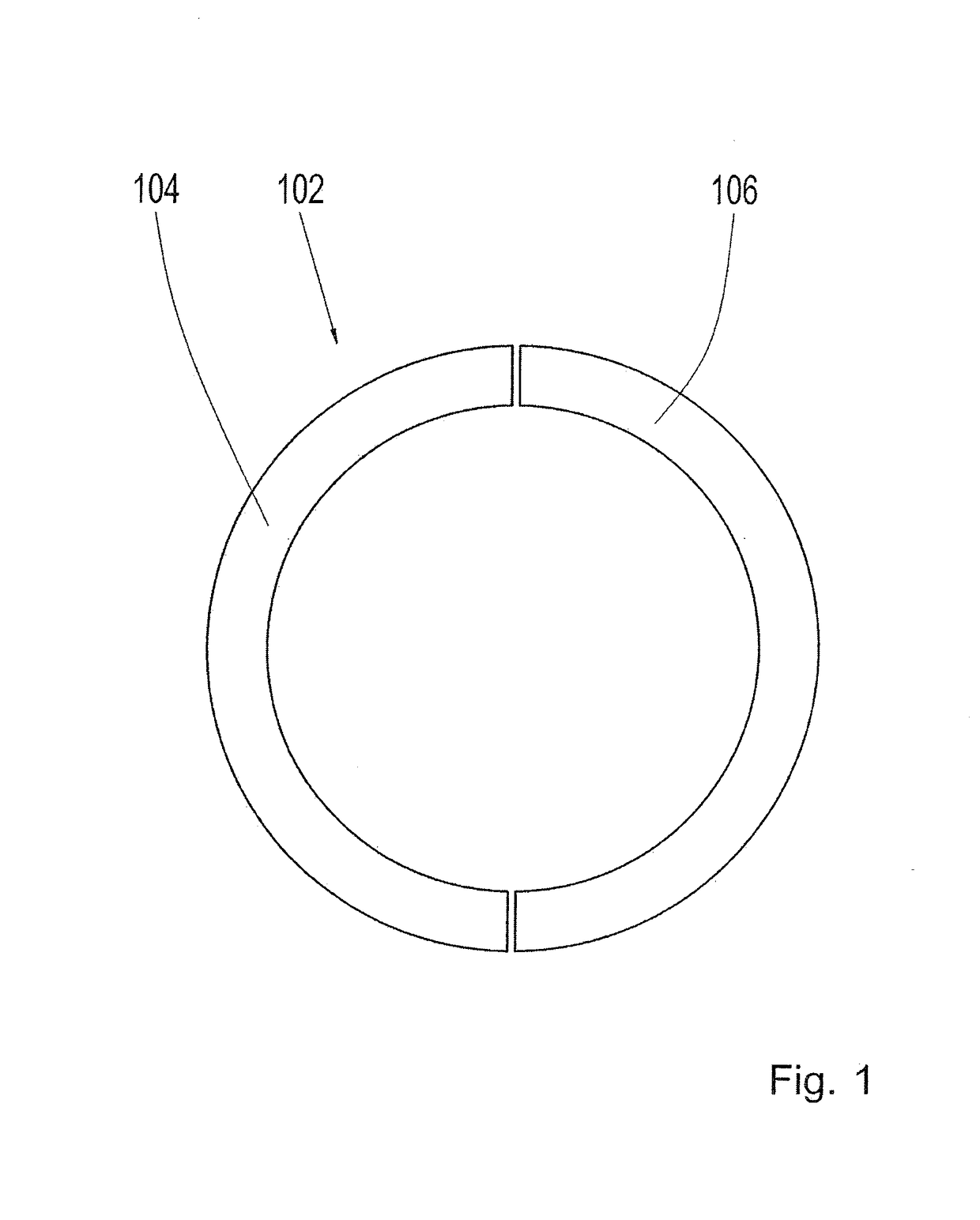
[0050]A first locking ring 102 according to FIG. 1 is designed in two pieces. The locking ring 102 consists of a first part 104 and a second part 106. Together, the first part 104 and the second part 106 have the form of a flat hollow cylinder with an annular base area.

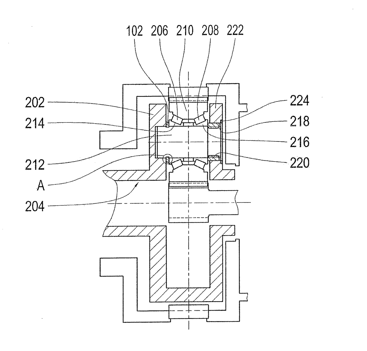
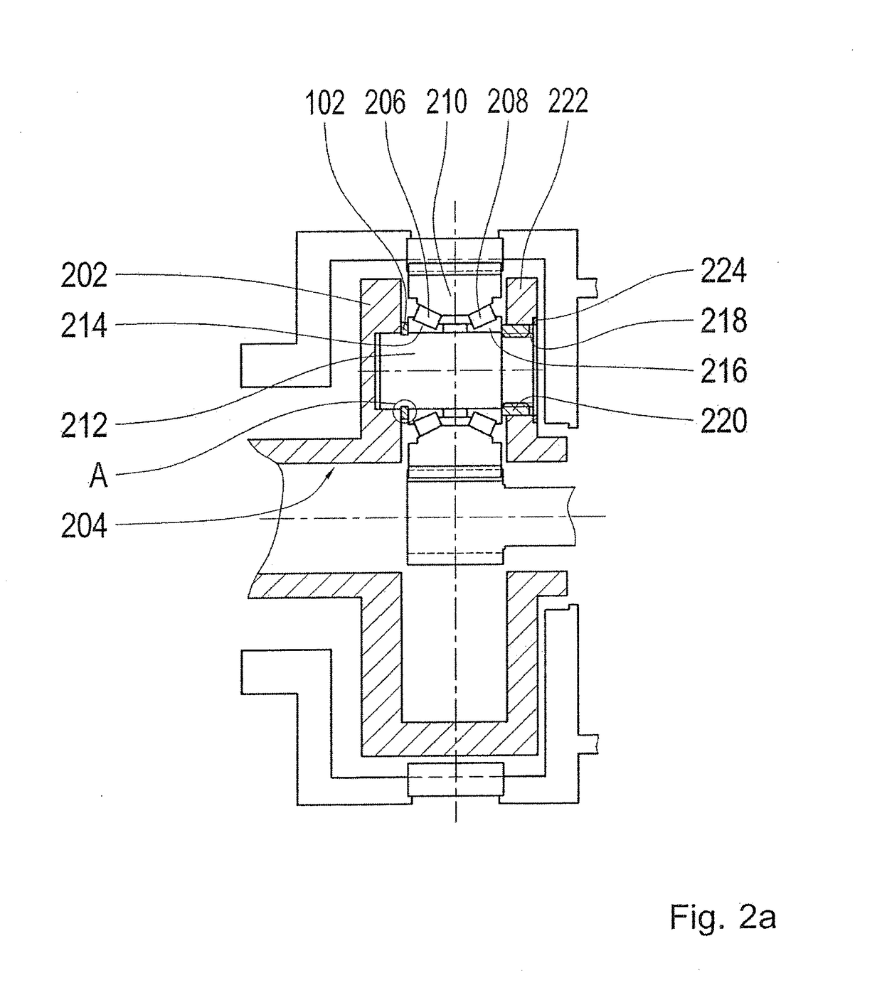
[0051]FIG. 2A shows how the first locking ring 102 is installed. The first locking ring 102 is situated between a first wall 202 of a planet carrier 204 and a first planet bearing 206. The first locking ring 102 thus separates the first wall 202 of the planet carrier 204 and the first planet bearing 206. Together with a second planet bearing 208, the first planet bearing 206 serves for rotational mounting of a planet gear 210 on a planetary pin 212. The first planet bearing 206 is, like the second planet bearing 208, designed as a tapered roller bearing. The inner bearing surface of the first planet bearing 206 forms a first inner ring 214. A second inner ring 216 is formed by the inner bearing surface of the second p...


PUM


Abstract

An arrangement for use, in particular, in the transmission of a wind turbine, having a planet carrier, at least one planet gear, at least one planetary pin and at least one bearing. The planet gear is mounted on the planetary pin, in a rotatable manner, by way of the at least one bearing. The arrangement has at least one nut and at least one first locking ring. The planetary pin has at least one shoulder and a thread. The first locking ring is mounted in such a way that the first locking ring can be supported against the shoulder in the axial direction. The nut is screwed onto the thread in such a way that the nut and the locking ring limit the axial play of the bearing, or such that the bearing is tensioned between the nut and the locking ring.

Description

[0001]This application is a National Stage completion of PCT / EP2015 / 063891 filed Jun. 22, 2015 which claims priority from German patent application no. 10 2014 214 295.4 filed Jul. 22, 2014.FIELD OF THE INVENTION[0002]The invention relates to an arrangement having a planet carrier, at least one planet gear, at least one planetary pin and at least one bearing as well as a method for mounting of such an arrangement.BACKGROUND OF THE INVENTION[0003]Such an arrangement is intended for use in a planet gear set, in particular in a planet gear set of a transmission of a wind turbine.[0004]Planet gear sets for wind turbines are known from the prior art, in which planet gear sets a planetary pin is fixed in a planet carrier in a force-locking manner. Prior to mounting of the planetary pin, the planet carrier is heated so that a shrink connection is created when the planetary pin has been introduced into the planet carrier and the planet carrier then cools down.[0005]The heating of the planet...

Claims


Application Information

Patent Timeline
IPC IPC(8): F16H57/08F16C25/06F16C33/58F16C19/38
CPCF16H57/082F16C19/386F16C25/06F16C2361/61F16H2057/085F16C2360/31F16C33/581F16H57/08F16C2226/60
Inventor SMOOK, WARRENDE SMET, JOBOGAERT, ROGER
Owner ZF FRIEDRICHSHAFEN AG
Learn More