Organic electroluminescent device

Inactive Publication Date: 2010-04-08
UDC IRELAND
View PDF6 Cites 6 Cited by
  • Summary
  • Abstract
  • Description
  • Claims
  • Application Information

AI Technical Summary

Benefits of technology

[0012]According to an aspect of the invention, an organic electroluminescent devic

Problems solved by technology

In JP-A-2005-48004, a carbazole material containing a deuterium atom and emitting phosphorescence at the ordinary temperature is used, but JP-A-20

Method used


Image

  • Organic electroluminescent device
  • Organic electroluminescent device
  • Organic electroluminescent device

Examples


examples

[0218]The invention will be described in further detail with reference to examples, but the invention should not be construed as being restricted thereto.

Synthesis of Exemplified Compound:

[0219]Exemplified compound (1-3) can be synthesized by coupling carbazole-d8 containing deuterium atoms on 1- to 8-positions described in Heterocycles, Vol. 67, No. 1, 353-359 (2006) with 4,4′-dibromobiphenyl by using a palladium catalyst or a copper catalyst.

[0220]Exemplified compound (4-3) can be synthesized by the coupling with 1,3-dibromobenzene in the same manner as in exemplified compound (1-3).

[0221]Exemplified compound (12-3) can be synthesized by the coupling with 3,6-dibromo-9-phenylcarbazole described in Tetrahedron, Vol. 54, No. 42, 12707-12714 (1998) in the same manner as in exemplified compound (1-3).

[0222]Exemplified compound (4-6) can be synthesized according to the following method.

[0223]Resorcinol-d6 can be synthesized according to the method described in J. Am. Chem. Soc., Vol. 1...


PUM

PropertyMeasurementUnit
Phosphorescence quantum yieldaaaaaaaaaa

Abstract

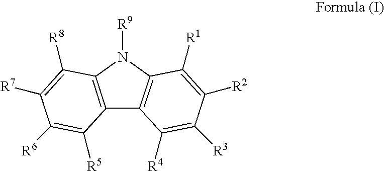
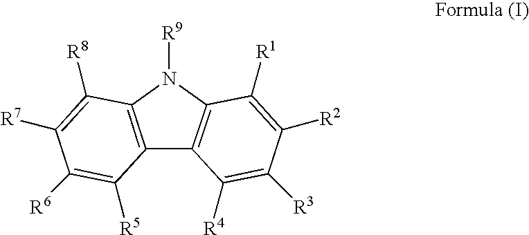
An organic electroluminescent device is provided and includes: a pair of electrodes; and at least one organic layer between the pair of electrodes, the at least one organic layer including a light-emitting layer. The at least one organic layer contains a compound represented by formula (I) below, and the light-emitting layer contains a phosphorescent material of a platinum complex having a tetradentate ligand.
R1 to R9 each independently represents a specific substituent.

Description

TECHNICAL FIELD[0001]The present invention relates to an organic electroluminescent device (hereinafter also referred to as “organic EL device”, “light-emitting device” or “device”) capable of emitting light by converting electric energy into light. In particular, the present invention relates to an organic electroluminescent device excellent in luminescent characteristics and durability.BACKGROUND ART[0002]Various types of display devices using organic light-emitting materials (organic luminescent devices) are actively researched and developed these days. Above all, organic EL devices are attracting public attention as promising display devices for capable of emitting lights of high luminance with low voltage.[0003]Also in recent years, the increase in efficiency of the devices has been advanced by the use of phosphorescent materials. As phosphorescent materials, iridium complexes and platinum complexes are known. (Refer to U.S. Pat. No. 6,303,238, WO 00 / 57676 and WO 00 / 70655.)[000...

Claims


Application Information

Patent Timeline
IPC IPC(8): H01J1/63
CPCC09K11/06H01L51/5016C09K2211/1011C09K2211/1014C09K2211/1029C09K2211/1044C09K2211/1059C09K2211/1088C09K2211/185H01L51/004H01L51/0043H01L51/0072H01L51/0081H01L51/0087H01L51/0094C09K2211/1007H10K85/141H10K85/151H10K85/346H10K85/324H10K85/40H10K85/6572H10K50/11H10K2101/10
Inventor TAKEDA, AKIRA
Owner UDC IRELAND
Why Eureka
Try Eureka