
Removal method, adhesive agent for substrate, and laminate including substrate

Inactive Publication Date: 2010-04-08
TOKYO OHKA KOGYO CO LTD
View PDF8 Cites 10 Cited by
  • Summary
  • Abstract
  • Description
  • Claims
  • Application Information

AI Technical Summary

Benefits of technology

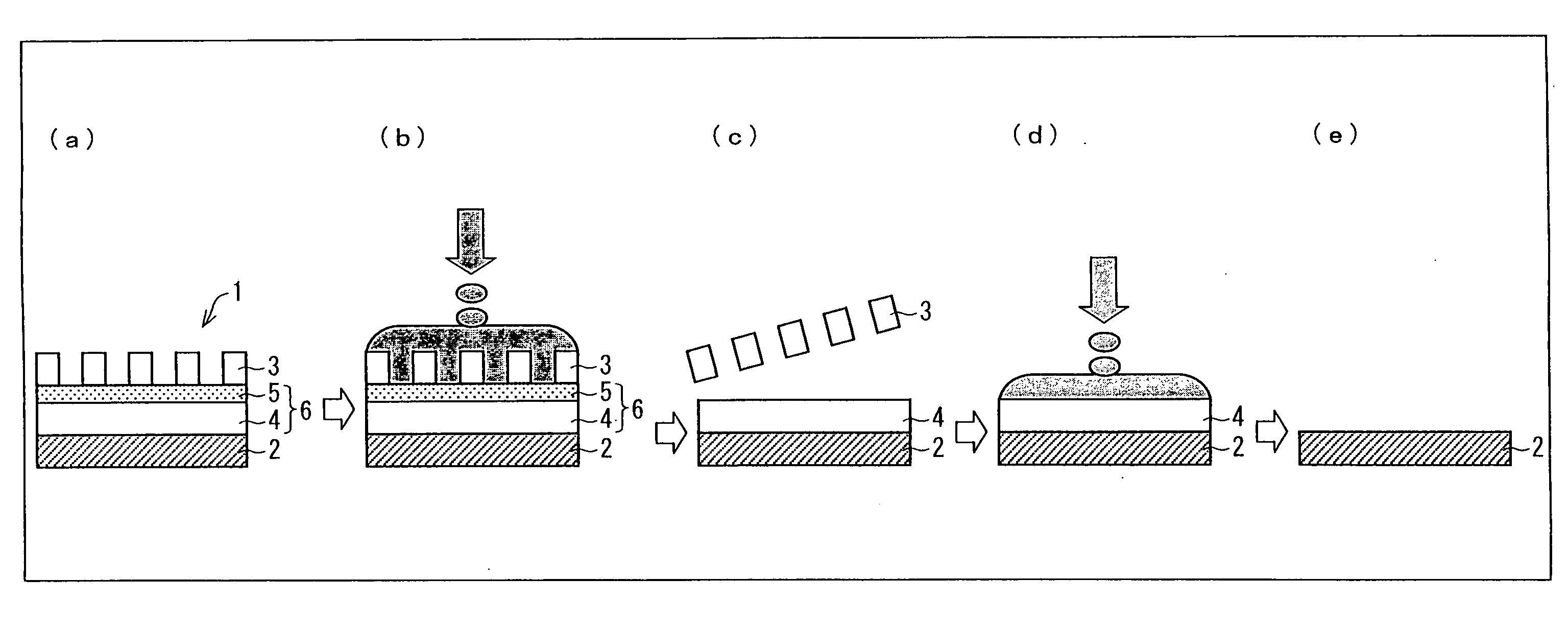
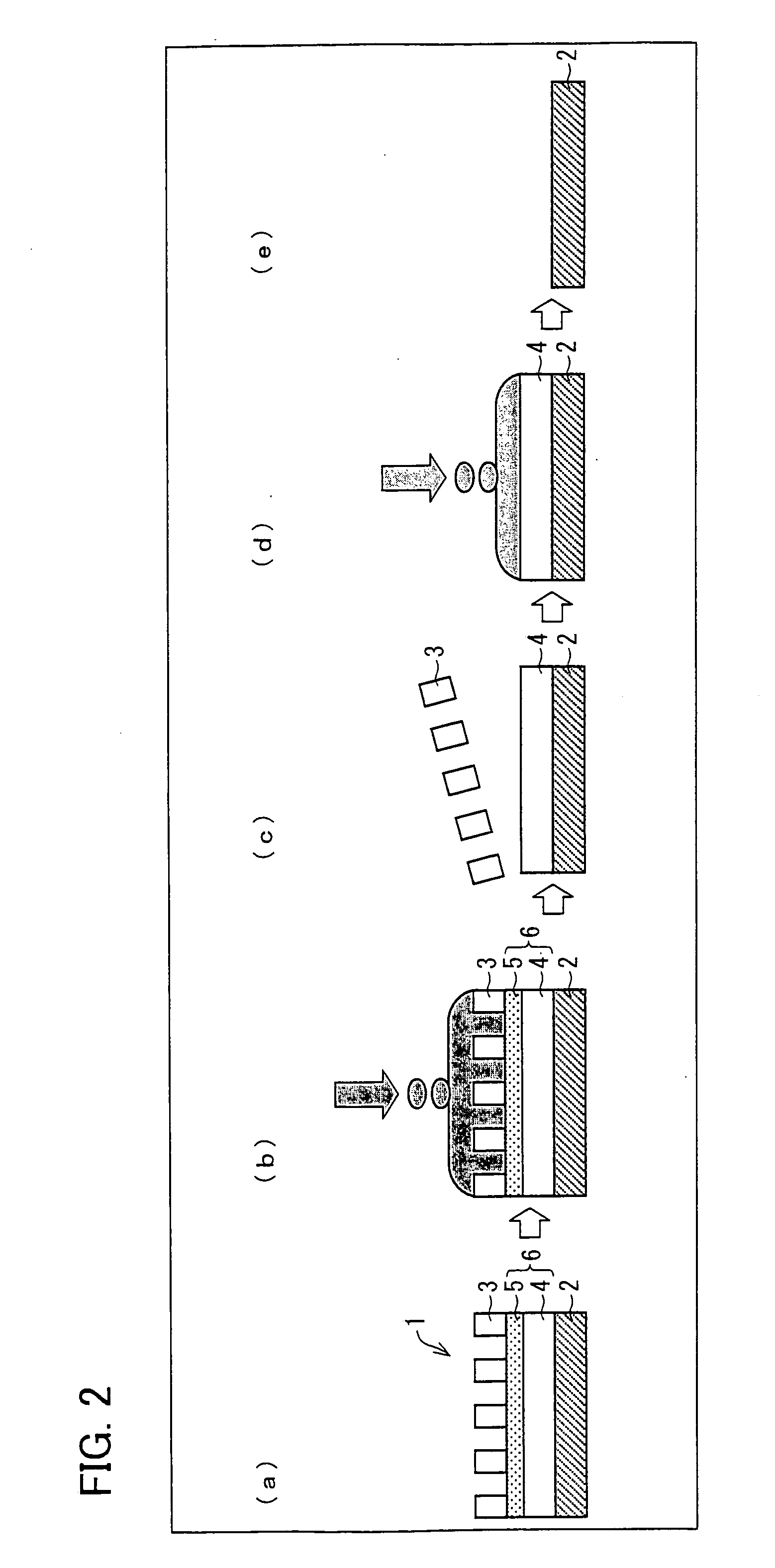
[0018]The removal method according to the present invention is the removal method includes: providing the support plate and the substrate being combined to each other via a first adhesive layer and a second adhesive layer, the second adhesive layer being (i) an adhesive layer which is dissolvable in a solvent quicker than the first adhesive layer or (ii) an adhesive layer which is dissolvable in a solvent different from a solvent to which the first adhesive layer is dissolvable, and the second adhesive layer being between the support plate and the first adhesive layer; and removing the support plate from the substrate by dissolving the second adhesive layer. Therefore, with the removal method according to the present invention, it is possible to remove the support plate from the substrate in a quick and easy way.

Problems solved by technology

However, a semiconductor wafer (hereinafter referred to as a wafer) from which the chip is produced is ground to have a thinner thickness and thereby has a weaker strength.
In addition, it is difficult to automatically transport the wafer having the weaker intensity due to the thin thickness.
As such, it is required to manually transport the wafer, and thus, handling of the wafer becomes complex.
As a result, it takes long time to remove the support plate from the wafer.

Method used


Image

  • Removal method, adhesive agent for substrate, and laminate including substrate
  • Removal method, adhesive agent for substrate, and laminate including substrate
  • Removal method, adhesive agent for substrate, and laminate including substrate

Examples


example 1

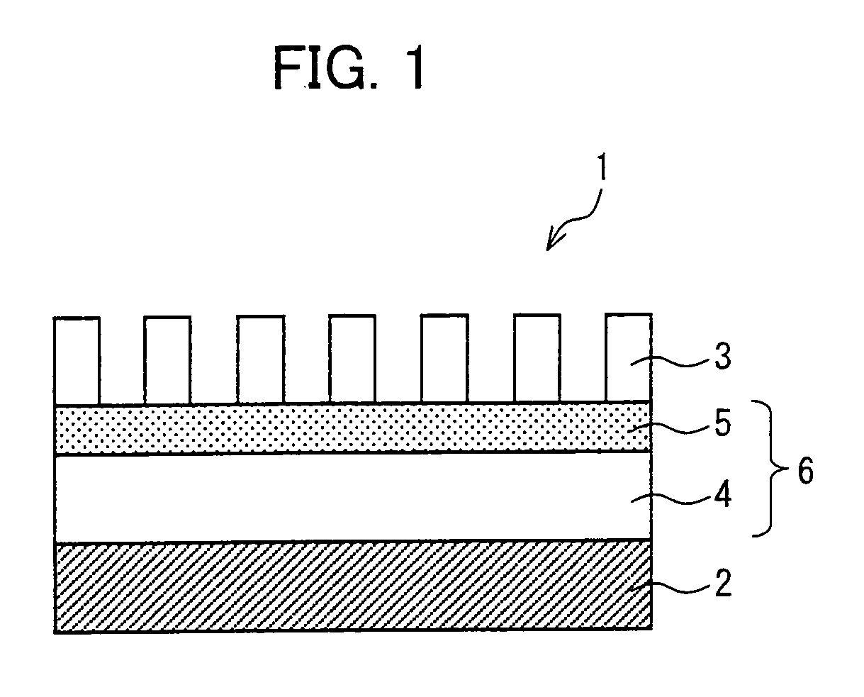
[0086]An adhesive compound 1 was applied onto a 5-inch silicon wafer 2 and then dried at 80° C. for 5 minutes, so as to form a first adhesive layer 4 having a film thickness of 15 μm. Subsequently, an adhesive compound 2 was applied onto the first adhesive layer 4 and then dried at 80° C. for 5 minutes, so as to form a second adhesive layer 5 having a film thickness of 3 μm. Then, a pored support plate 3 was attached on the second adhesive layer 5.

[0087]HP was poured onto a laminate 1 formed in the above way, from above the support plate 3. To HP, the second adhesive layer 5 had a solution rate of 200 nm / sec. After the second adhesive layer 5 was dissolved, the support plate 3 was removed, and HP was poured onto an entire surface of the first adhesive layer 4. To HP, the first adhesive layer had a solution rate of 100 nm / sec. It took approximately 60 seconds to dissolve the first adhesive layer 4, and approximately 2 minutes and 30 seconds to dissolve the support plate 3.

example 2

[0088]In a same way as Example 1, the adhesive compound 1 was applied onto a 5-inch silicon wafer 2, and dried at 80° C. for 5 minutes, so as to form a first adhesive layer 4 having a film thickness of 15 μm. On the first adhesive layer 4, subsequently, a solution of collagen peptide (a solution of collagen peptide having 30 mass %) was applied and dried at 80° C. for 5 minutes, so as to form a second adhesive layer 5 having a film thickness of 3 μm. Then, a pored support plate 3 was attached on the second adhesive layer 5.

[0089]Water was poured onto a laminate 1 formed in the above way, from above the support plate 3. To water, the second adhesive layer 5 had a solution rate of 340 nm / sec. After the second adhesive layer 5 was dissolved, the support plate 3 was removed, and HP was poured onto an entire surface of the first adhesive layer 4. To HP, the first adhesive layer 4 had a solution rate of 100 nm / sec. It took approximately 60 seconds to dissolve the first adhesive layer 4, a...

example 3

[0090]An adhesive compound 1 was applied onto a 6-inch silicon wafer 2 and dried at 110° C. for 3 minutes and then at 150° C. for 6 minutes, so as to form a first adhesive layer 4 having a film thickness of 30 μm. Subsequently, a p-menthane solution (30 mass %) containing a hydrogenerated terpene resin (YASUHARA CHEMICAL Co., Ltd) was applied onto the first adhesive layer 4 and dried at 120° C. for 3 minutes, so as to form a second adhesive layer 5 having a film thickness of 7 μm. Then, a pored support plate 3 was attached on the second adhesive layer 5.

[0091]p-menthane was poured onto a laminate 1 formed in the above way, from above the support plate 3. To p-menthane, the second adhesive layer 5 had a solution rate of 400 nm / s. After the second adhesive layer 5 was dissolved, the support plate 3 was removed, and HP was poured onto an entire surface of the first adhesive layer 4. To HP, the first adhesive layer had a solution rate of 100 nm / s. It took approximately 60 seconds to dis...


PUM

PropertyMeasurementUnit
Fractionaaaaaaaaaa
Temperatureaaaaaaaaaa

Abstract

The removal method of the present invention includes: providing a support plate and a substrate being combined to each other via a first adhesive layer and a second adhesive layer, the second adhesive layer being an adhesive layer which is dissolvable in a solvent quicker than the first adhesive layer or an adhesive layer which is dissolvable in a solvent different from a solvent to which the first adhesive layer is dissolvable, and the second adhesive layer being between the support plate and the first adhesive layer; and removing the support plate from the substrate by dissolving the second adhesive layer. Further, the removal method of the present invention includes, after the step of removing, dissolving the first adhesive layer. This removes the support plate from the wafer in a quick and easy way.

Description

[0001]This Nonprovisional application claims priority under 35 U.S.C. §119(a) on Patent Application No. 2008-258237 filed in Japan on Oct. 3, 2008, and on Patent Application No. 2009-140223 filed in Japan on Jun. 11, 2009, the entire contents of which are hereby incorporated by reference.TECHNICAL FIELD[0002]The present invention relates to (i) a removal method for removing a support plate from a substrate to which the support plate is adhered, (ii) an adhesive agent for the substrate, and (iii) a laminate including the substrate.BACKGROUND ART[0003]As a mobile phone, a digital AV device, an IC card, and the like product are improved in their functionality, it is increasingly demanded that a semiconductor chip (hereinafter referred to as a chip) which is to be mounted be downsized and thinned, so that the chip can be integrated in a package with higher density. In order to achieve high-density integration of the chip in the package, it is necessary to thin a thickness of the chip to...

Claims


Application Information

Patent Timeline
IPC IPC(8): B32B9/04B29C63/00B32B23/04
CPCB32B7/06B32B7/12B32B9/04B32B37/12Y10T156/1111B32B2457/14C09J5/00C09J2205/302B32B43/006B32B27/06B32B3/266B32B2255/00B32B2255/26B32B2255/28B32B2307/748H01L21/6835H01L2221/68318H01L2221/68327H01L2221/6834H01L2221/68381Y10T428/31971Y10T428/31504C09J2301/502C09J101/02C09J129/04C09J145/00H01L21/304
Inventor ASAI, TAKAHIROMISUMI, KOICHIIMAI, HIROFUMI
Owner TOKYO OHKA KOGYO CO LTD
Learn More