
Spinal correction device

a technology for spinal cord and spine, which is applied in the field of spinal cord correction devices, can solve the problems of complex structure of the positioning mechanism device for such adjustment and the large size of the device, and achieve the effects of stabilizing the posture of the user, short oscillation, and quick oscillation

Active Publication Date: 2010-04-08
FUKUNAGA MIKIO
View PDF13 Cites 10 Cited by
  • Summary
  • Abstract
  • Description
  • Claims
  • Application Information

AI Technical Summary

Benefits of technology

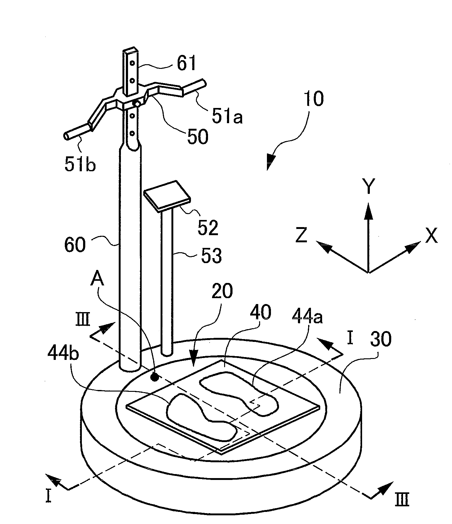
[0012]According to the device of the present invention, the spinal column is twisted, thereby stretching the transversospinal muscle of an erector spinal muscle segment into a stretched state, in accordance with spinal distortion. Then, motion is imparted to symmetrical positions on each side of the spinal column of the user to swing the lumbar region, thereby stabilizing the position of the lumbar region and transmitting short, quick oscillation to the vertebrae of the spinal column. Particularly, this oscillation is absorbed in the section where spinal distortion has occurred, causing the transversospinal muscle related to that section to repeatedly shift from a stretched state to an even further stretched state. That is, with the device, it is possible to simply correct a spinal column in which distortion has occurred without requiring precise adjustment of the relative positional relationship of the user and the spinal correction device. According to such an invention, a mechanism for positioning the user to the spinal correction device is not needed, making it possible to achieve a device that is small in size and easily assembled.
[0013]According to the device of the above-described invention, said lower limb exercising part may swing said lumber region via both limbs with said user in a standing state. From the lower limbs, motion is imparted to horizontally symmetrical positions of the pelvis with respect to the spinal column. The lower limb exercising part imparts motion to horizontally symmetrical positions of the pelvis with respect to the spinal column to swing the lumbar region of the user, thereby stabilizing the position of the lumbar region and transmitting short, quick oscillation to the vertebrae.
[0015]According to the device of the above-described invention, said lower limb exercising part may be a footboard that swings about an axis causing the underside surfaces of the feet of said lower limbs of said user to incline backwards and forwards, with said axis arranged directly beneath the spinal column of said user. With the axis that extends in the horizontal direction of the user arranged directly beneath the spinal column so that the underside surfaces of the feet of the lower limbs of the user are caused to incline backwards and forwards, vertical motion of respectively opposite phases is imparted to anteroposterior symmetrical positions of the pelvis with respect to the spinal column. The motion performed when the user attempts to balance in a standing position is thus achieved and short, quick oscillation is transmitted to the vertebrae.
[0016]According to the device of the above-described invention, said pair of gripping parts may be provided at both ends of a single rod arranged horizontally. The user can suitably select whether to grip the gripping parts in a supinated position or a pronated position. Particularly, in a case where the gripping parts are gripped in a supinated position, the underarms of the upper limbs become more tightened than in a case where the gripping parts are gripped in a pronated position, thereby stabilizing the position of the trunk. With this arrangement, the oscillation is sufficiently absorbed in the section where spinal distortion had occurred, causing the transversospinal muscle related to that section to repeatedly shift from a stretched state to an even further stretched state.
[0017]According to the device of the above-described invention, said rod may swing while maintaining a horizontal position in the circumference of a rotational axis in the vicinity of the center in the longitudinal direction. With the introduction of oscillation from both upper limbs to the shoulder region with the spinal column therebetween, the center axis of the twist of the spinal column following the longitudinal direction of the spinal column is defined, thereby stabilizing the posture of the user.

Problems solved by technology

The structure of a positioning mechanism device for such adjustment becomes complicated, and such a device tends to be large in size.

Method used


Image

  • Spinal correction device
  • Spinal correction device
  • Spinal correction device

Examples


Embodiment Construction

[0025]First, the principle behind achieving the spinal correction effect according to the present invention will be described.

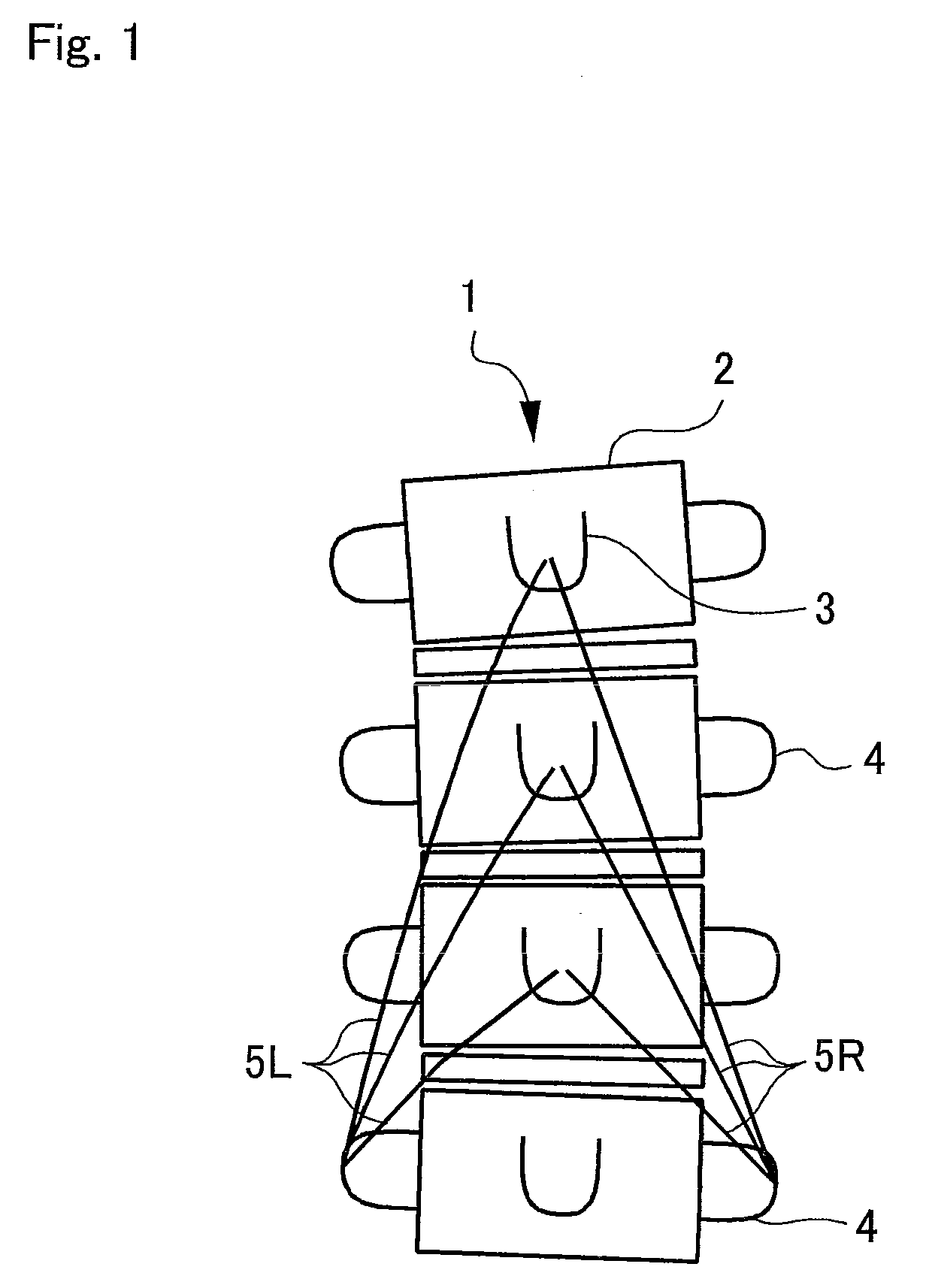
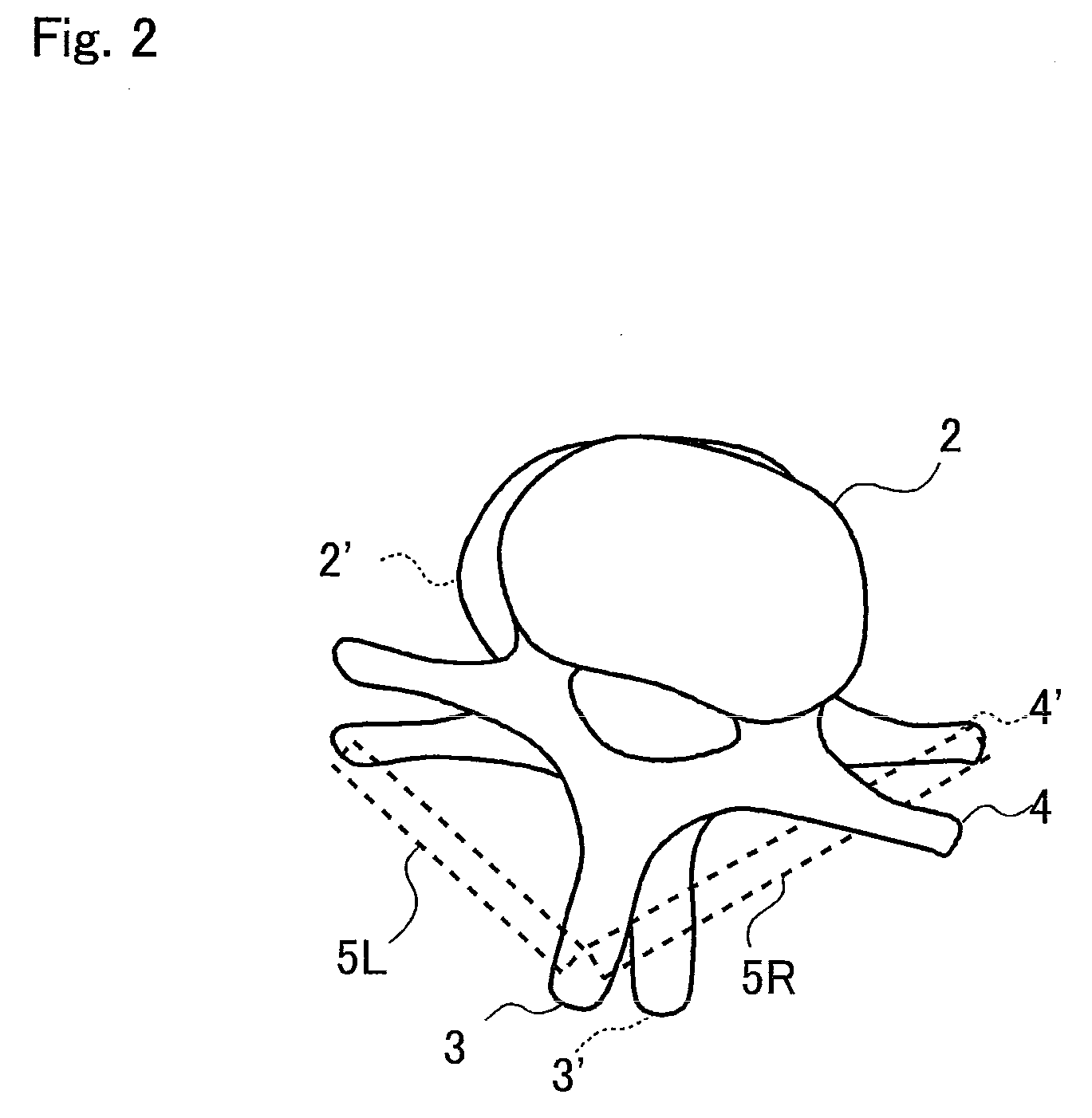
[0026]As illustrated in FIG. 1, transversospinal muscles 5L and 5R of an erector spinal muscle segment (not shown) for supporting a vertebra 2 constituting a spinal column 1 are muscles that connect a transverse process 4 lateral to the vertebra 2 and a spinous process 3 rearward to (on the rear side of) the vertebra 2. When the spinal column is laterally bent, for example, one transversospinal muscle 5R of the left and right transversospinal muscles (5L and 5R) stretches. If the person is healthy, the lateral bend of the spinal column 1 is resolved by the contractile force of the transversospinal muscle 5R. Nevertheless, in a case where the contractile force of the transversospinal muscle 5R has decreased, the lateral bend of the spinal column 1 cannot be resolved. The spinal column 1 that cannot fully resolve a lateral bend, that is, the spinal column 1 hav...


PUM


Abstract

A spinal correction device that corrects the spinal column of a user comprising a lower limb exercising part that swings the lumber region to impart a symmetrical motion to positions symmetrical with respect to the spinal column of a user facing forward with his or her trunk erect, a pair of gripping parts provided in a position in front of the lower limb exercising part and gripped by both hands of the user, and a control unit that relatively moves the gripping parts with respect to the lower limb exercising part between the position in front of the lower limb exercising part and a lateral position, with the lower limb exercising part in a driven state.

Description

BACKGROUND OF THE INVENTION[0001]1. Field of the Invention[0002]The present invention relates to a spinal correction device for correcting the spinal column of a user.[0003]2. Description of the Background Art[0004]When a person's spinal column is corrected by a chiropractor, for example, correction is made by employing displacement to the vertebrae by use of his hands to adjust the position of the vertebrae.[0005]There is also a method in which a spinal column correction effect is achieved by stimulating the erector spinal muscle segment that supports the vertebrae constituting the spinal column by chiropractor's hands, which activates the contractile force of the erector spinal muscle segment.[0006]For example, in a case where a transversospinal muscle of an erector spinal muscle segment has been fully stretched as a result of spinal distortion, this method imparts a motion that repeatedly pulls the muscle to an even further stretched state, inducing activation of the contractile ...

Claims


Application Information

Patent Timeline
IPC IPC(8): A63B26/00A61F5/00
CPCA61H1/005A63B2230/62A61H23/0254A61H2201/1215A61H2201/1418A61H2201/1635A61H2201/164A61H2201/1678A61H2205/081A63B21/00178A63B22/16A63B23/0233A63B2023/003A63B2071/0652A63B2208/0204A61H1/0292
Inventor FUKUNAGA, MIKIO
Owner FUKUNAGA MIKIO
Learn More