Apodized aspheric diffractive lenses

a technology of aspheric diffractive lenses and apodized aspheric diffractive lenses, which is applied in the field of multi-focal diffractive ophthalmic lenses, can solve the problems of varying diffractive effect and conventional multifocal diffractive lenses, and achieve the effect of enhancing image contrast and enhancing image contras

Inactive Publication Date: 2010-04-08
NOVARTIS AG
View PDF19 Cites 46 Cited by
  • Summary
  • Abstract
  • Description
  • Claims
  • Application Information

AI Technical Summary

Benefits of technology

[0005]The present invention generally provides multifocal ophthalmic lenses, such as intraocular and contact lenses, that employ aspherical surface profiles to enhance image contrast, particularly at a far focus of the lens. In many embodiments, the invention provides pseudoaccommodative lenses having at least one aspherical surface for enhancing image contrast.
[0006]In one aspect, the present invention provides a diffractive lens, such as a pseudoaccommodative intraocular lens (IOL), that includes an optic having an aspherical base curve, and a plurality of annular diffractive zones superimposed on a portion of the base curve so as to generate a far focus and a near focus. The aspherical base curve enhances image contrast at the far focus of the optic relative to that obtained by a substantially identical IOL in which the respective base curve is spherical.
[0019]In another aspect, the present invention provides a pseudoaccommodative apodized diffractive IOL that includes an optic having an anterior surface and a posterior surface, wherein at least one of the surfaces includes an aspherical base profile and a plurality of diffractive zones superimposed on a portion of the base profile such that each zone is disposed at a selected radius from an optical axis of the optic and is separated from an adjacent zone by a step. This lens surface can further include a peripheral region surrounding the diffractive zones. The diffractive zones generate a far focus and a near focus and the aspherical profile enhances the image contrast at the far focus relative to that obtained by a substantially identical lens having a spherical profile.
[0020]In other aspects, the present invention provides a pseudoaccommodative, diffractive IOL that includes an optic formed of a biocompatible polymeric material and having a posterior surface and an anterior surface, where the optic provides a near focus and a far focus. At least one of the anterior or the posterior surfaces can be characterized by a base curve and a plurality of diffractive zones disposed as annular concentric diffractive elements about an optical axis, where each has a height relative to the base curve that progressively decreases as a distance of the diffractive element from the optical axis increases. The base curve can exhibit an aspherical profile for enhancing the image contrast at the far focus for pupil diameters in a range of about 4 to about 5 millimeters relative to a substantially identical IOL in which the base curve is spherical.
[0021]In other aspects, the invention provides an apodized diffractive ophthalmic lens that includes an optic having an anterior surface and a posterior surface, at least one of which has an aspherical base profile and a plurality of annular diffractive zones disposed on the base profile for generating a near focus and a far focus. The aspherical profile enhances an image contrast at the far focus relative to that obtained by a substantially identical lens in which a respective base profile is spherical. The ophthalmic lens can be, without limitation, an intraocular lens or a contact lens.

Problems solved by technology

Conventional multifocal diffractive lenses, however, are not designed so as to control or modify aberrations of the natural eye such that the combined lens and the patient eye would provide enhanced image contrast.
Moreover, the design of apodized diffractive lenses for providing better image contrast can present difficulties in that such lenses exhibit a varying diffractive effect at different radial locations across the lens.

Method used


Image

  • Apodized aspheric diffractive lenses
  • Apodized aspheric diffractive lenses
  • Apodized aspheric diffractive lenses

Examples


Embodiment Construction

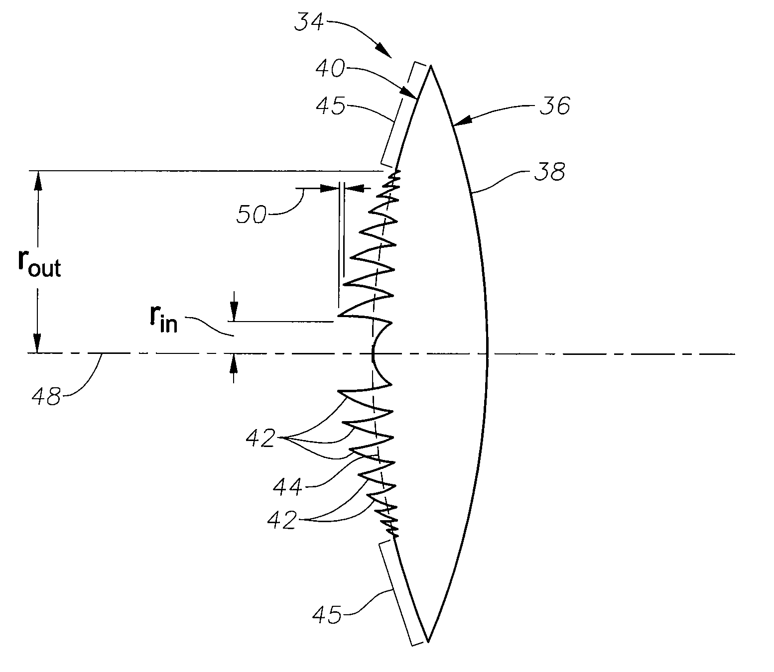
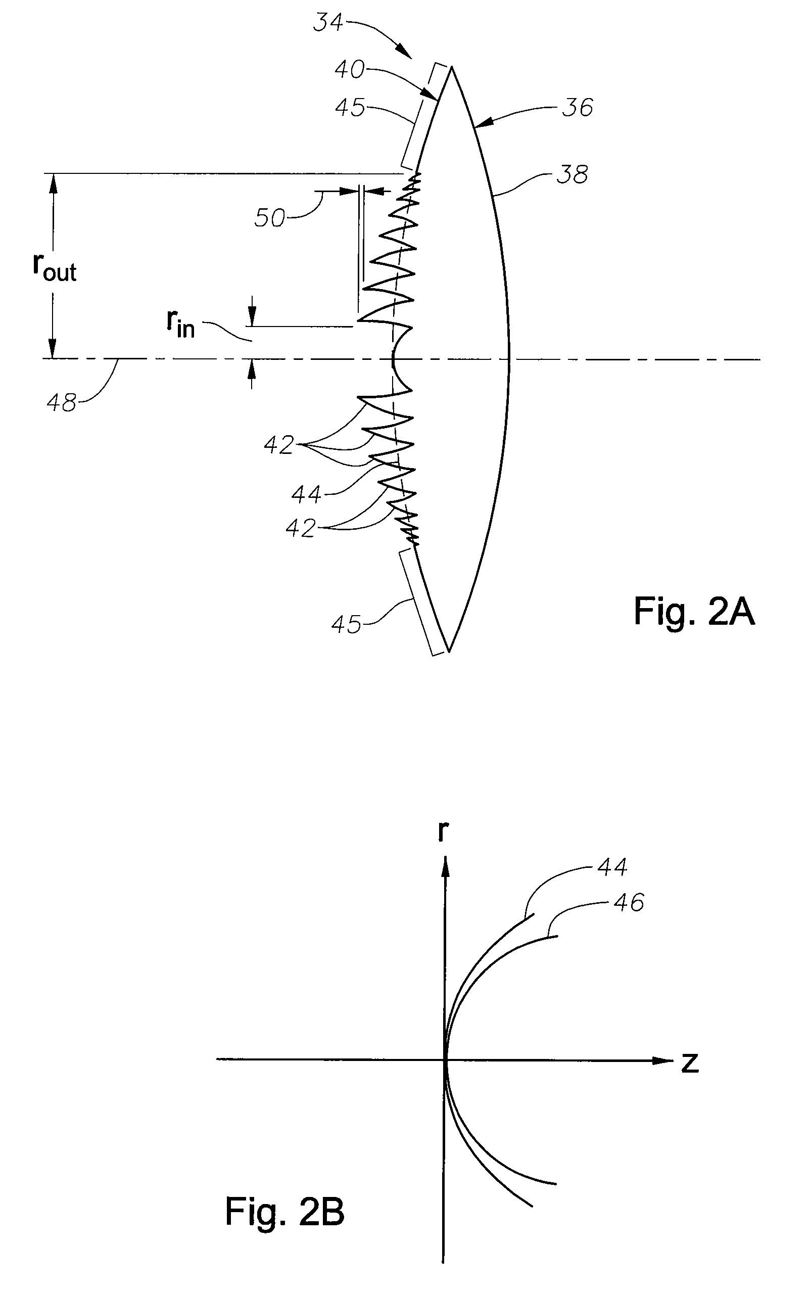
[0041]The present invention provides multifocal ophthalmic lenses that include at least one aspherical lens surface having an asphericity selected to improve image contrast relative to that provided by a substantially identical lens in which the respective surface is spherical. In the embodiments below, the teachings of the invention are illustrated primarily in connection with intraocular lenses. It should, however, be understood that these teachings apply equally to a variety of other ophthalmic lenses, such as contact lenses.

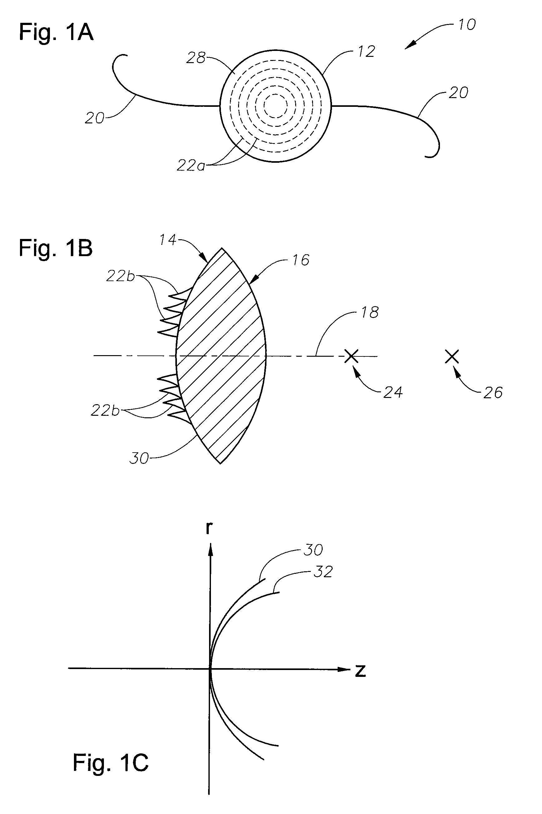
[0042]FIGS. 1A and 1B schematically illustrate a multifocal diffractive intraocular lens 10 according to one embodiment of the invention having an optic 12 that includes an anterior surface 14 and a posterior surface 16. In this embodiment, the anterior surface and the posterior surface are symmetric about an optical axis 18 of the lens, although asymmetric surfaces can also be employed. The lens further includes radially extending fixation members or haptics...


PUM


Abstract

Aspheric diffractive lenses are disclosed for ophthalmic applications. For example, multifocal intraocular lens (IOLs) are disclosed that include an optic having an anterior surface and a posterior surface, at least one of which surfaces includes an aspherical base profile on a portion of which a plurality of diffractive zones are disposed so as to generate a far focus and a near focus. The aspherical base profile enhances image contrast at the far focus of the lens relative to that obtained by a substantially identical IOL in which the respective base profile is spherical.

Description

[0001]This application is a continuation of U.S. application Ser. No. 11 / 000,770 filed Dec. 1, 2004.TECHNICAL FIELD OF THE INVENTION[0002]The present invention relates generally to multifocal diffractive ophthalmic lenses and, more particularly, to apodized diffractive intraocular lenses that can provide enhanced image contrast.[0003]Periodic diffractive structures can diffract light simultaneously into several directions, also typically known as diffraction orders. In multifocal intraocular lenses, two diffraction orders are utilized to provide a patient with two optical powers, one for distance vision and the other for near vision. Such diffractive intraocular lenses are typically designed to have an “add” power that provides a separation between the far focus and the near focus. In this manner, a diffractive intraocular lens can provide a patient in whose eye the lens is implanted with vision over a range of object distances. For example, a diffractive IOL can replace a patient's...

Claims


Application Information

Patent Timeline
Patent Type & Authority Applications(United States)
IPC IPC(8): A61F2/16G02C7/06G02C7/04G02B5/18
CPCA61F2/1618G02C2202/20A61F2002/164A61F2/1654A61F2/164A61F9/008A61F9/013A61F2/16G02C7/06
Inventor SIMPSON, MICHAEL J.
Owner NOVARTIS AG
Why Eureka
Try Eureka