Storage system

a storage system and storage technology, applied in the field of storage systems, can solve the problems of insufficient ssd and bottlenecks in the configuration of the interface, and achieve the effect of improving the performance of the storage system

Active Publication Date: 2010-04-08
HITACHI LTD
View PDF22 Cites 64 Cited by
  • Summary
  • Abstract
  • Description
  • Claims
  • Application Information

AI Technical Summary

Benefits of technology

[0021]According to the embodiments of the invention, it is possible to improve performance of a storage system.

Problems solved by technology

The transfer rate is sufficient for the hard disk drive, but it is not sufficient for the SSD.
That is, the semiconductor memory may read and write data at high speed, and thus the configuration of the interface may become a bottleneck.

Method used


Image

  • Storage system
  • Storage system
  • Storage system

Examples


first embodiment

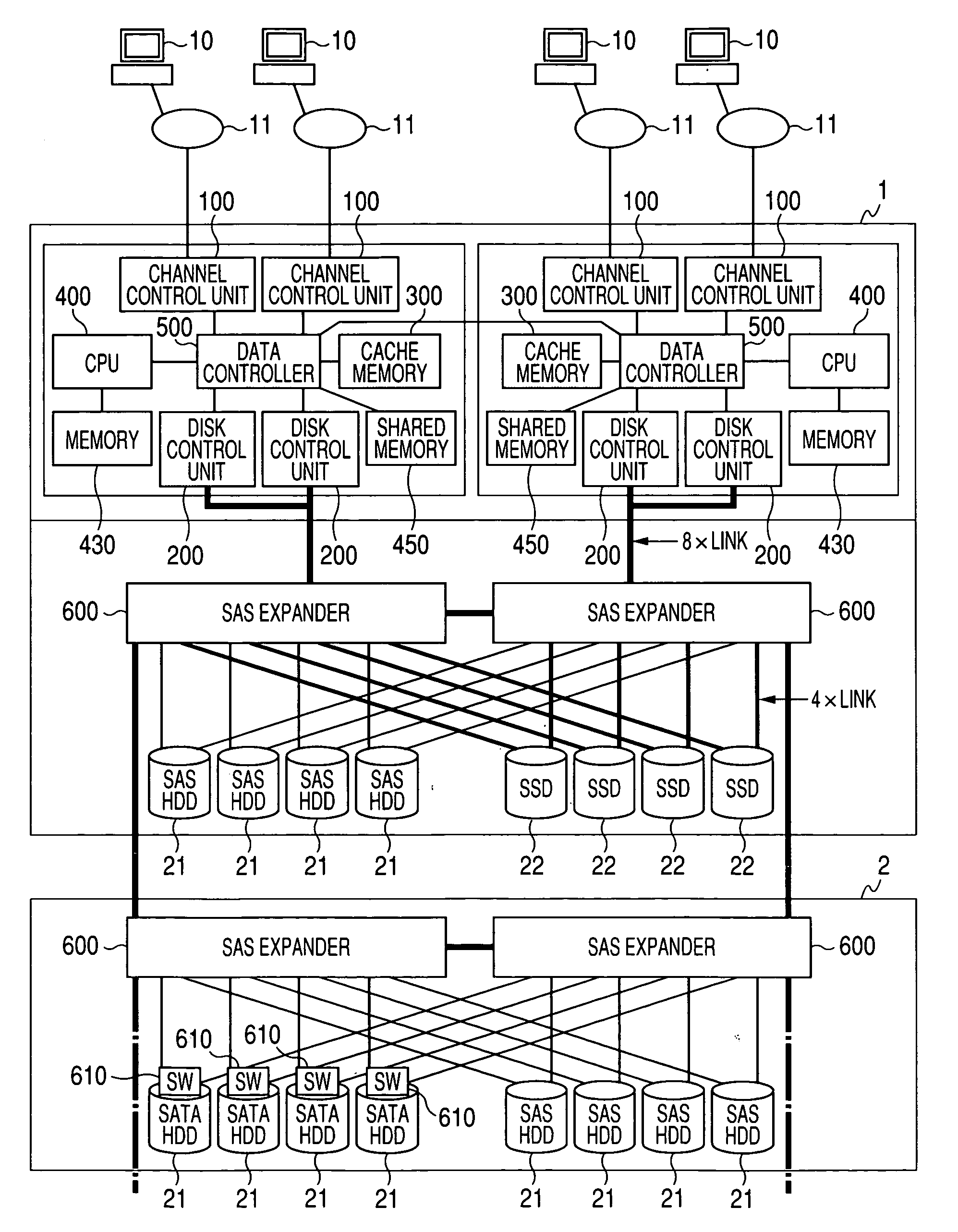
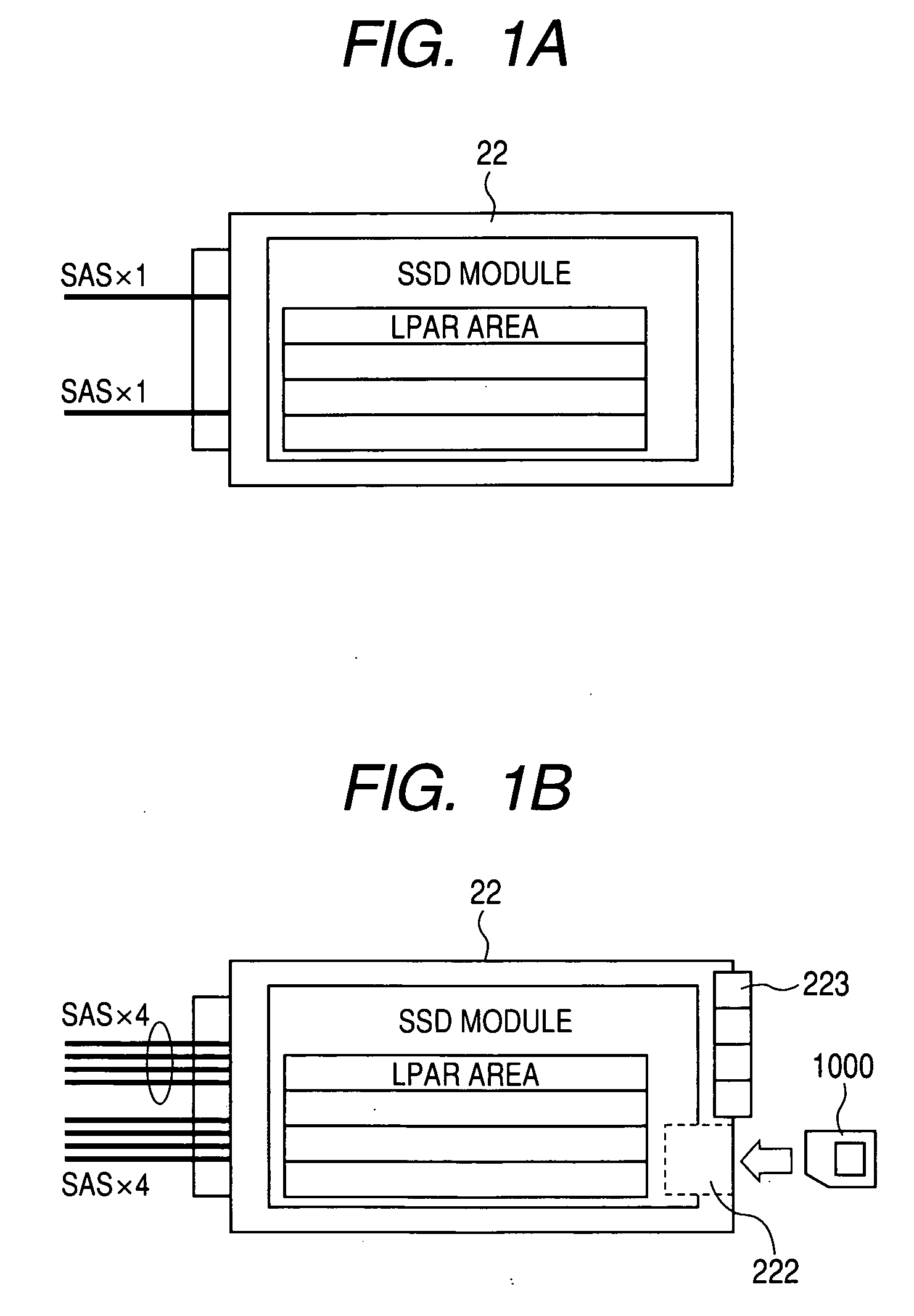
[0057]FIGS. 1A and 1B are explanatory views showing the overview of a first embodiment of the invention.

[0058]In general, a storage device 22 has one or a plurality of physical ports for data input / output. As shown in FIG. 1A, for example, a storage apparatus having an SAS interface has two physical ports. One of the two physical ports is used as an active port, and the other physical port is used as a standby port. Active and standby paths for data transfer with respect to a disk control unit are set by the ports. For this reason, even if the storage area of the storage device is logically partitioned, the partitioned storage areas are not mapped to the ports.

[0059]In contrast, as shown in FIG. 1B, a storage device of the first embodiment has eight physical ports. Of these, four ports may be used as active ports, and the other four ports may be used as standby ports. Paths for data transfer with respect to the disk control unit are set by the ports. In this case, four ports maybe i...

second embodiment

[0206]Next, a second embodiment of the invention will be described.

[0207]In the known storage system, a verification code is added to data in a predetermined write unit with respect to the storage apparatus to verify that data is correct. For example, in case of a semiconductor memory (so-called SSD) and an SATA disk drive, a verification code, such as LA or LRC, is added to data for every 512 bytes. In case of an FC disk drive, a verification code is added to data for every 520 bytes.

[0208]When the controller issues a write command to the storage apparatus, data may not be written in the storage apparatus.

[0209]For this reason, in the related art, after data is written, written data is read, and comparison is performed between write data and read data by one byte. Alternatively, comparison is performed between all the verification code of write data and all the verification code of read data.

[0210]However, in the known method, a transfer bandwidth is used in order to read out all w...


PUM


Abstract

Disclosed is a storage system that suppress occurrence of a bottleneck in the storage system, efficiently uses a bandwidth of hardware, and achieves high reliability. A storage system includes a storage apparatus that stores data, a controller that controls data input/output with respect to the storage apparatus, and an interface that couples the storage apparatus and the controller. The storage apparatus has a plurality of physical ports that are coupled to the interface. The controller logically partitions a storage area of the storage apparatus into a plurality of storage areas and provides the plurality of storage areas, or allocates the plurality of physical ports to the logically partitioned storage areas.

Description

CROSS REFERENCES TO RELATED APPLICATIONS[0001]This application relates to and claims priority from Japanese Patent Application No. 2008-261997, filed on Oct. 8, 2008, the entire disclosure of which is incorporated herein by reference.BACKGROUND OF THE INVENTION[0002]1. Field of the Invention[0003]The present invention relates to a storage system, and in particular, a technology that speeds up a storage system and improves reliability.[0004]2. Description of the Related Art[0005]In a storage system (disk array device), an increase in capacity of a storage module such as a hard disk drive (HDD) or a Solid State Drive (“SSD” or “semiconductor memory storage device”) leads to an increase in capacity of a group (a RAID group or a storage pool) having the storage module.[0006]In many cases, an upper limit capacity of a logical volume (LU) on the group having the storage module is 2 TB. The reason for the upper limit capacity is that an LBA specified area as parameters of the READ(10) comm...

Claims


Application Information

Patent Timeline
Patent Type & Authority Applications(United States)
IPC IPC(8): G06F12/02G06F12/08G06F12/00
CPCG06F3/0613Y02B60/1225G06F3/0622G06F3/0635G06F3/0637G06F3/0658G06F3/0685G06F11/201G06F11/2089G06F11/2094G06F12/0804G06F12/0866G06F3/0619G06F3/0665G06F3/0689G06F3/0617Y02D10/00G06F3/0634G06F3/061G06F3/0614G06F3/0629G06F3/0679
Inventor MOTONAGA, MAMORUCHIKUSA, TAKASHINOZAWA, TAKASHIMATSUI, YUKOHOKAZONO, MEGUMI
Owner HITACHI LTD
Why Eureka
Try Eureka