

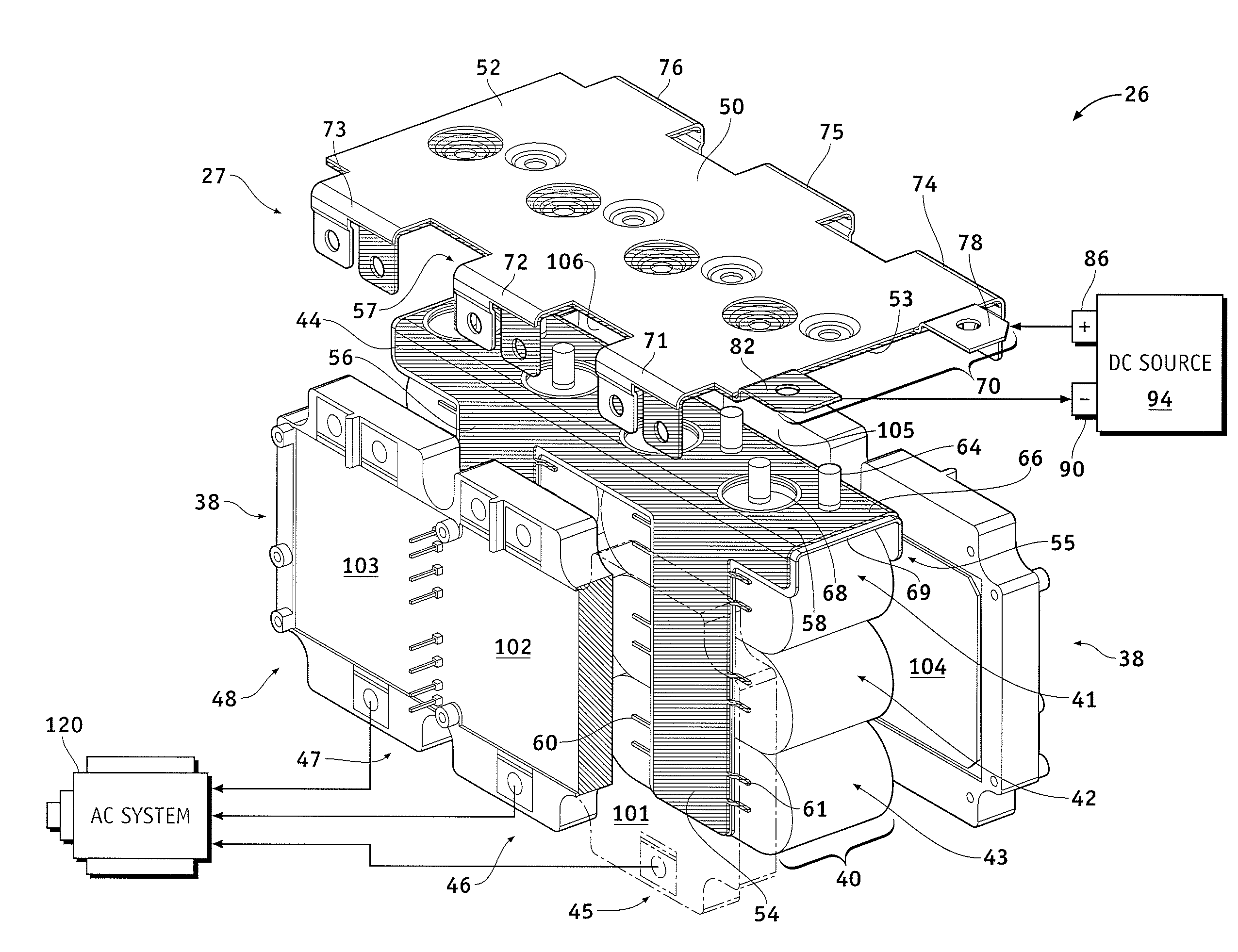
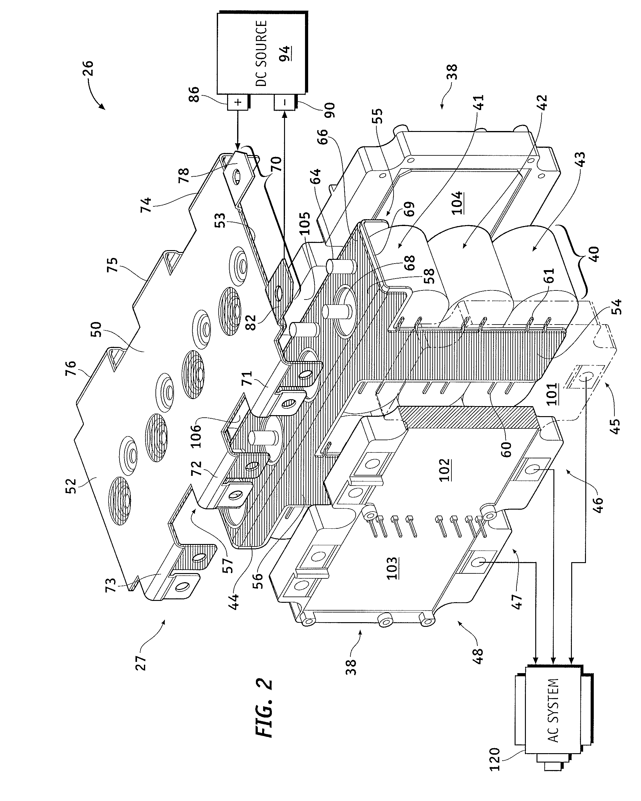
Low inductance busbar
a low-inductance, busbar technology, applied in the direction of power conversion systems, printed circuit board receptacles, electric cable installations, etc., can solve the problems of relatively complex busbars, and high cost of materials and assembly, and achieve relatively large voltage spikes
- Summary
- Abstract
- Description
- Claims
- Application Information
AI Technical Summary
Benefits of technology
Problems solved by technology
Method used
Image

Examples
Embodiment Construction
[0013]The following description refers to elements or nodes or features being “connected” or “coupled” together. As used herein, unless expressly stated otherwise, “connected” means that one element / node / feature is directly joined to (or directly communicates with) another element, node or other feature in a mechanical, logical, electrical or other appropriate sense. Likewise, unless expressly stated otherwise, “coupled” means that one element / node / feature is directly or indirectly joined to (or directly or indirectly communicates with) another element / node / feature in a mechanical, logical, electrical or other appropriate sense. The term “exemplary” is used in the sense of “example,” rather than “model.” Further, although the figures may depict example arrangements of elements, additional intervening elements, devices, features, or components may be present in a practical embodiment of the invention. Furthermore, the term “integrally formed” or “integrally connected” means that a fi...
PUM
 Abstract
Description
Claims
Application Information