Device and method for producing shuttering elements
a technology of shuttering elements and shuttering, which is applied in clay preparation apparatus, transportation and packaging, chemistry apparatus and processes, etc., can solve the problem that no visual detectability of identification elements can prevent intentional removal, and achieve the effect of simple and economical
- Summary
- Abstract
- Description
- Claims
- Application Information
AI Technical Summary
Benefits of technology
Problems solved by technology
Method used
Image

Examples
first embodiment
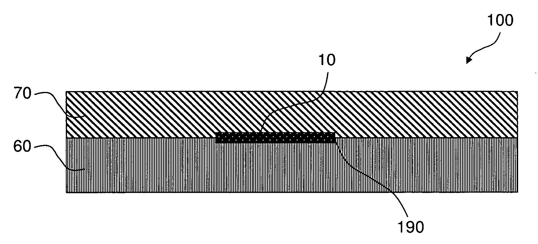
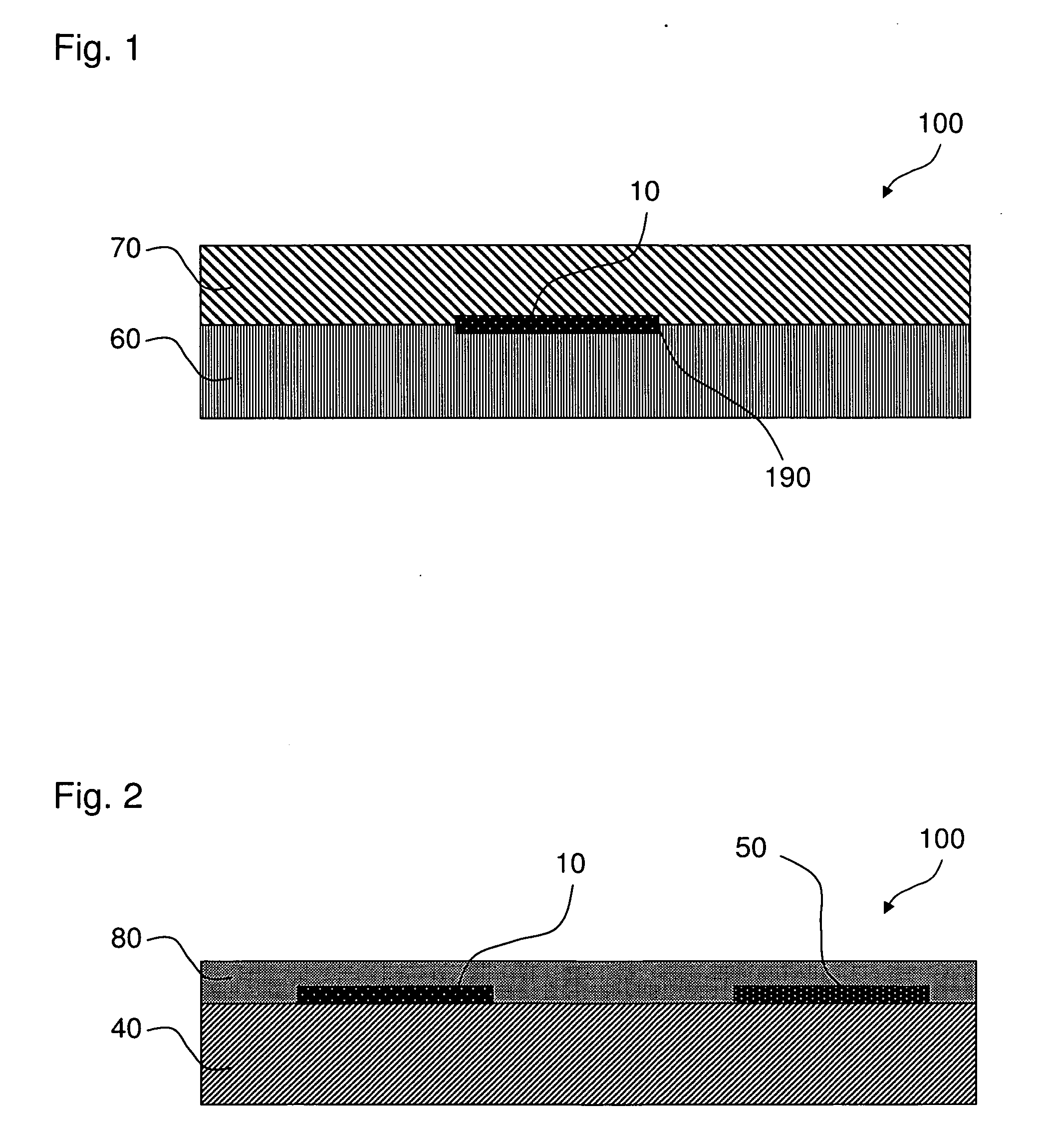
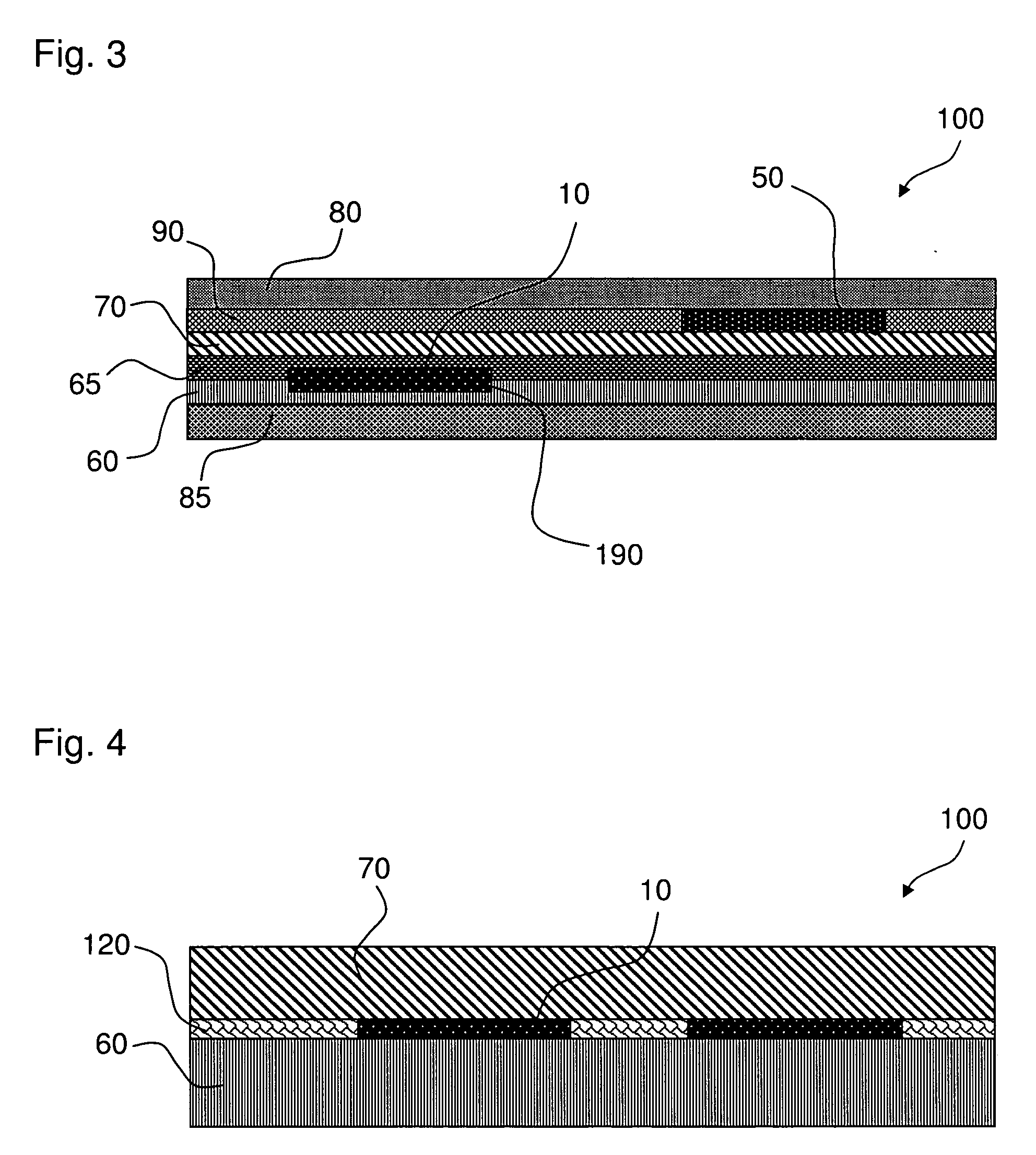
[0085]FIGS. 1 to 6 are showing schematically particularly preferred designs of a formwork element according to the invention. The multilayer panel 100 which is shown in FIG. 1 consists, according to the invention, of a first layer 60 and a second layer 70, which can consists of different materials. In an embodiment which is not shown, the two layers can be as well manufactured from the same material. Some materials are proved as particularly robust and resistant, which fulfill the high standards to the load capacity and the modulus of elasticity (measurement for the rigidity).
[0086]Here, usually it concerns wood, respectively wood composite materials, which can be manufactured by pressing of different wood parts like panels, rods, veneer, veneer strips, splinters and fibres with adhesive or bonding agents. The different wood components can be arbitrarily arranged in their dimensions and strength, as well as regarding their position. Commercial panels are for example OSB chip boards,...
second embodiment
[0111]FIGS. 8 to 11 are showing schematically particularly preferred figures of the formwork element according to the invention. The FIG. 8 exemplarily shows a top view of a frame element 200, which can embed the multilayer panel at the edges. The frame element 200 shown here is described by a circular right-angled profile, whereby the height of the edge profile matches with the height of a multilayer panel 100, in order to reduce unevenness, or visible transitions resulting from the use such form-worked concrete surfaces, to a minimum. In order to increase the torsion rigidity and to reach a maximum of dimension accuracy, reinforcing struts 220 are fixed to the frame element 200.
[0112]In order to be able to fix a perfectly fitted multilayer panel 100 in the frame element 200, hole supports 230 are mounted onto the frame element 200, so that a fixed or detachable connexion, for example with rivets or screws can be made possible. According to the invention, it is of big advantage tha...
third embodiment
[0138]FIG. 22 however shows exemplarily a schematic perspective view of the formwork element according to the invention, whereby also logos 490 or advertisement can be attach to the coating of the formwork beam 400 in order to increase the recognition-effect for example. The above described embodiments of a formwork element according to the invention are also presented in combination.
PUM
| Property | Measurement | Unit |
|---|---|---|
| Fraction | aaaaa | aaaaa |
| Fraction | aaaaa | aaaaa |
| Frequency | aaaaa | aaaaa |
Abstract
Description
Claims
Application Information