Piston for internal combustion engines

a technology for internal combustion engines and piston rings, which is applied in the direction of machines/engines, brake systems, transportation and packaging, etc., can solve the problems of reducing the effective contact pressure and consequently the wear of the ring contact face during engine operation, so as to reduce localized wear, reduce the risk of failure, and increase the edge life

Active Publication Date: 2010-04-15
MAHLE INT GMBH +1
View PDF11 Cites 28 Cited by
  • Summary
  • Abstract
  • Description
  • Claims
  • Application Information

AI Technical Summary

Benefits of technology

[0013]The object of the present invention is to provide a piston ring for internal combustion engines which shows reduced localized wear at the butt end regions, thus increasing its edge life and minimizing the risk of a failure due to overpressure at the butt end regions.SUMMARY OF THE INVENTION
[0015]The ring contact face of the piston ring according to the invention therefore has two regions, starting from each butt end, which have a different shape compared with the remaining ring contact face. Thus, with regard to the cross-section of the ring contact face, its profile becomes less barreled in direction of the butt ends, i.e. its curvature becomes more flat (or less domed) when approaching the butt ends, said butt ends being regions where usually a higher wear occurs. Consequently, over the butt end regions the ring contact face shows a larger contact area with regard to the cylinder wall, thus reducing the effective contact pressure and consequently the wear of the ring contact face during operation of the engine.
[0016]Therefore, in this differentiated region of the barrel-shaped profile of the ring contact face, a better seating contact distribution occurs between the ring contact face and the adjacent wall of the engine cylinder, resulting in a minimization of wear and an increase of the edge life of the piston ring according to the invention and an increase of the engine service life as well.

Problems solved by technology

Consequently, over the butt end regions the ring contact face shows a larger contact area with regard to the cylinder wall, thus reducing the effective contact pressure and consequently the wear of the ring contact face during operation of the engine.

Method used


Image

  • Piston for internal combustion engines
  • Piston for internal combustion engines
  • Piston for internal combustion engines

Examples


Embodiment Construction

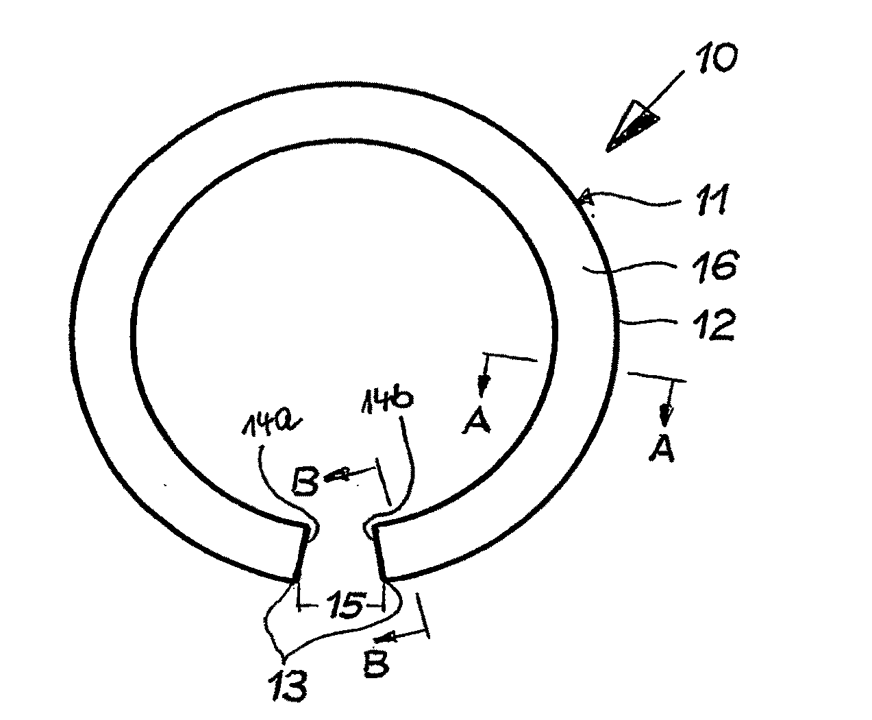
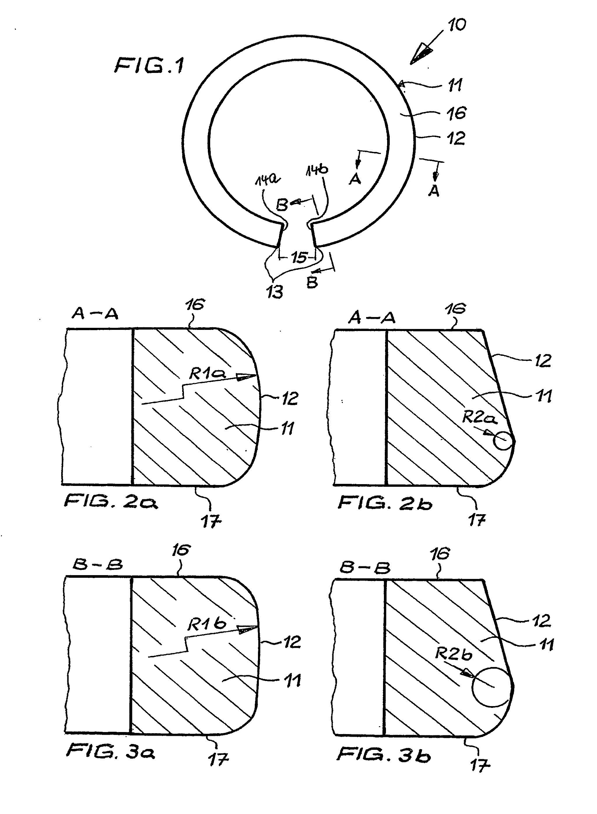
[0025]FIG. 1 represents a schematic view of an embodiment of a piston ring 10 according to the invention. The piston ring 10 comprises a ring body 11 with an upper side face 16, a lower side face 17 and an outer ring contact face 12 to contact a cylinder wall during operation of the engine (not shown). The piston ring 10 further comprises a ring joint 13 with two butt ends 14a, 14b facing each other and defining a ring gap 15.

[0026]FIGS. 2a, 2b depict schematic cross-sectional views of symmetric (FIG. 2a) and asymmetric (FIG. 2b) barrel-shaped ring contact faces 12 at a position A-A along the piston ring perimeter. FIG. 2b shows that in case of an asymmetric barrel-shaped ring contact face 12 the highest point of the profile exhibiting a maximum curvature is slightly displaced to the lower side face 17 of the piston ring body 11.

[0027]FIGS. 3a, 3b depict schematic cross-sectional views of symmetric (FIG. 3a) and asymmetric (FIG. 3b) barrel-shaped ring contact faces 12 at a position ...


PUM

PropertyMeasurementUnit
angleaaaaaaaaaa
angleaaaaaaaaaa
angleaaaaaaaaaa

Abstract

The present invention relates to a piston ring (10), particularly a compression ring, for an internal combustion engine, comprising a ring-shaped body (11) having a ring joint formed by butt ends (14a, 14b), the ring-shaped body (11) further having a ring contact face (12) along its perimeter, for contacting a cylinder wall in operation. According to the invention, the ring contact face (12) has a barrel-shaped profile, the barrel-shaped profile having in any of its cross-sections an area of maximum curvature, whose radius of curvature increases in the direction of the butt ends (14a, 14b).

Description

FIELD OF INVENTION[0001]The present invention refers to a piston ring for an internal combustion engine and, more particularly, to a compression piston ring, comprising a ring-shaped body having a ring joint formed by butt ends.BACKGROUND ART[0002]In internal combustion engines, the piston ring shows a barrel profile on its contact face against a cylinder wall of the combustion engine. The barrel profile may be symmetrical or more commonly asymmetrical. If asymmetrical, the highest point of the profile exhibiting a maximum curvature is slightly displaced to the ring lower flank.[0003]In operation of the combustion engine, the ring profile changes due to wear, assuming a slightly conical shape. The worn profile has strong influence on oil scraping and the contact pressure distribution, and consequently on the ring wear rate.[0004]Due to the engine operating conditions, the temperature on the ring inside diameter is greater than on the outside diameter. Such thermal gradient causes a ...

Claims


Application Information

Patent Timeline
Patent Type & Authority Applications(United States)
IPC IPC(8): F16J9/14B23P15/06
CPCF16J9/14Y10T29/49282F16J9/20
Inventor TOMANIK, ANTONIO EDUARDO MEIRELLESCIMINELLI DUARTE DE SOUZA, MAURICIO
Owner MAHLE INT GMBH
Why Eureka
Try Eureka