
Windmill-type electric generation system

a technology of electric generation system and windmill, which is applied in the direction of electric generator control, machines/engines, mechanical equipment, etc., can solve the problems of increasing the cost of installing difficulty in maintaining windmill-type electric generation system, and difficulty in adjusting the direction of rotary blade units, so as to reduce the length and weight of each rotary blade unit, reduce the effect of weight and easy and convenient transportation

Inactive Publication Date: 2010-04-15
HONG GU DUCK
View PDF8 Cites 18 Cited by
  • Summary
  • Abstract
  • Description
  • Claims
  • Application Information

AI Technical Summary

Benefits of technology

"The present invention provides a windmill-type electric generation system that includes four rotary blade units mounted on the rotary shafts in pairs, with each unit having a different length and weight. This makes it easy to transport and install the rotary blade units in steep and arduous regions. The rotary blade units are disposed at both sides of the supporting post, which eliminates problems caused by eccentricity. The system also includes a power transmission mechanism that allows the rotary blade units to rotate in opposite directions, maximizing the electricity generation efficiency."

Problems solved by technology

However, the conventional windmill-type electric generation system has drawbacks in that the costs necessary for installing the windmill-type electric generation system are increased due to the provision of the plurality of electric generators, and it is difficult to maintain the windmill-type electric generation system.
In this case, however, it is difficult to adjust the directions of the rotary blade units such that the rotary blade units face toward the blowing direction of wind.

Method used


Image

  • Windmill-type electric generation system
  • Windmill-type electric generation system
  • Windmill-type electric generation system

Examples


Embodiment Construction

[0016]Now, a preferred embodiment of the present invention will be described in detail with reference to the accompanying drawings.

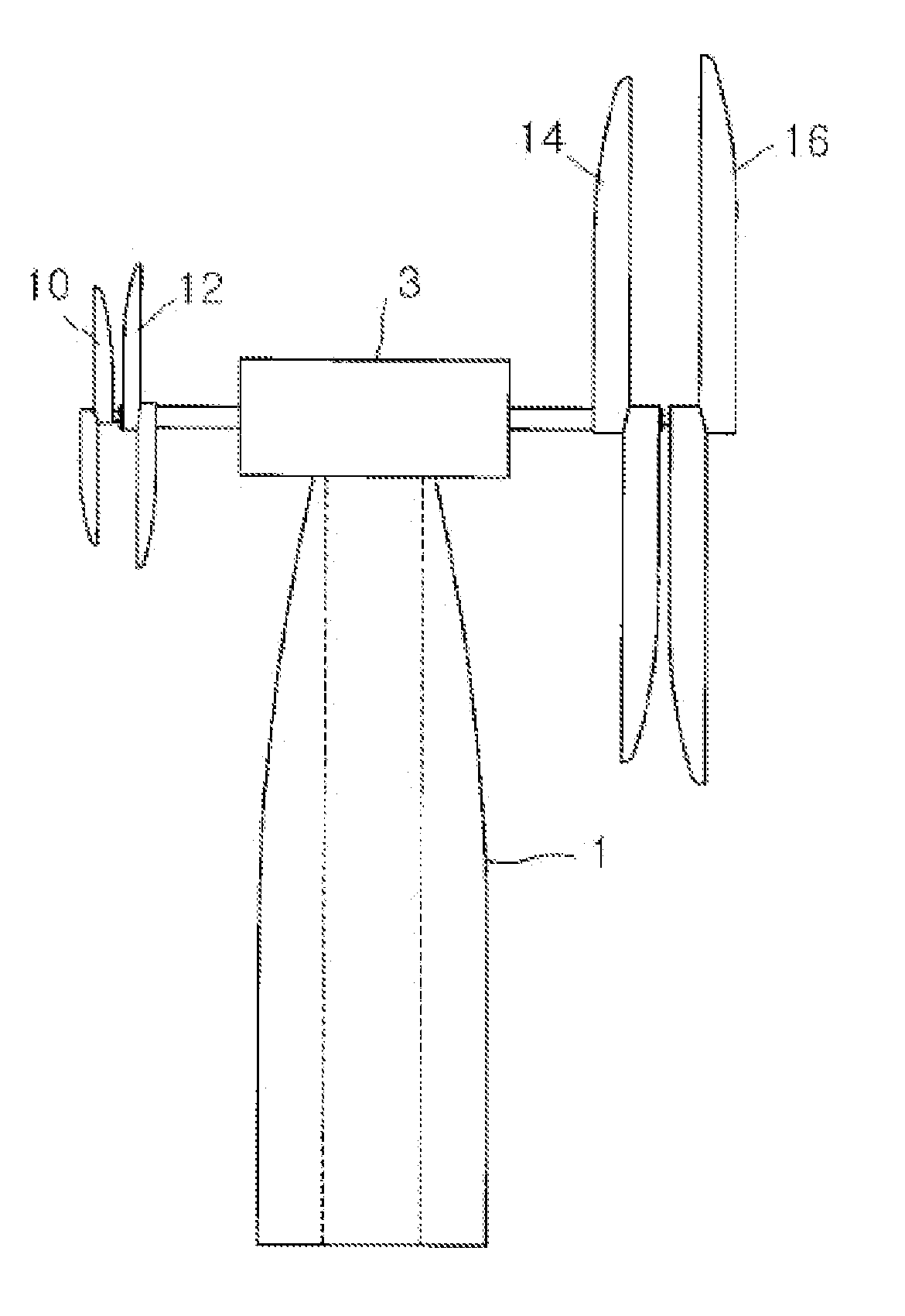
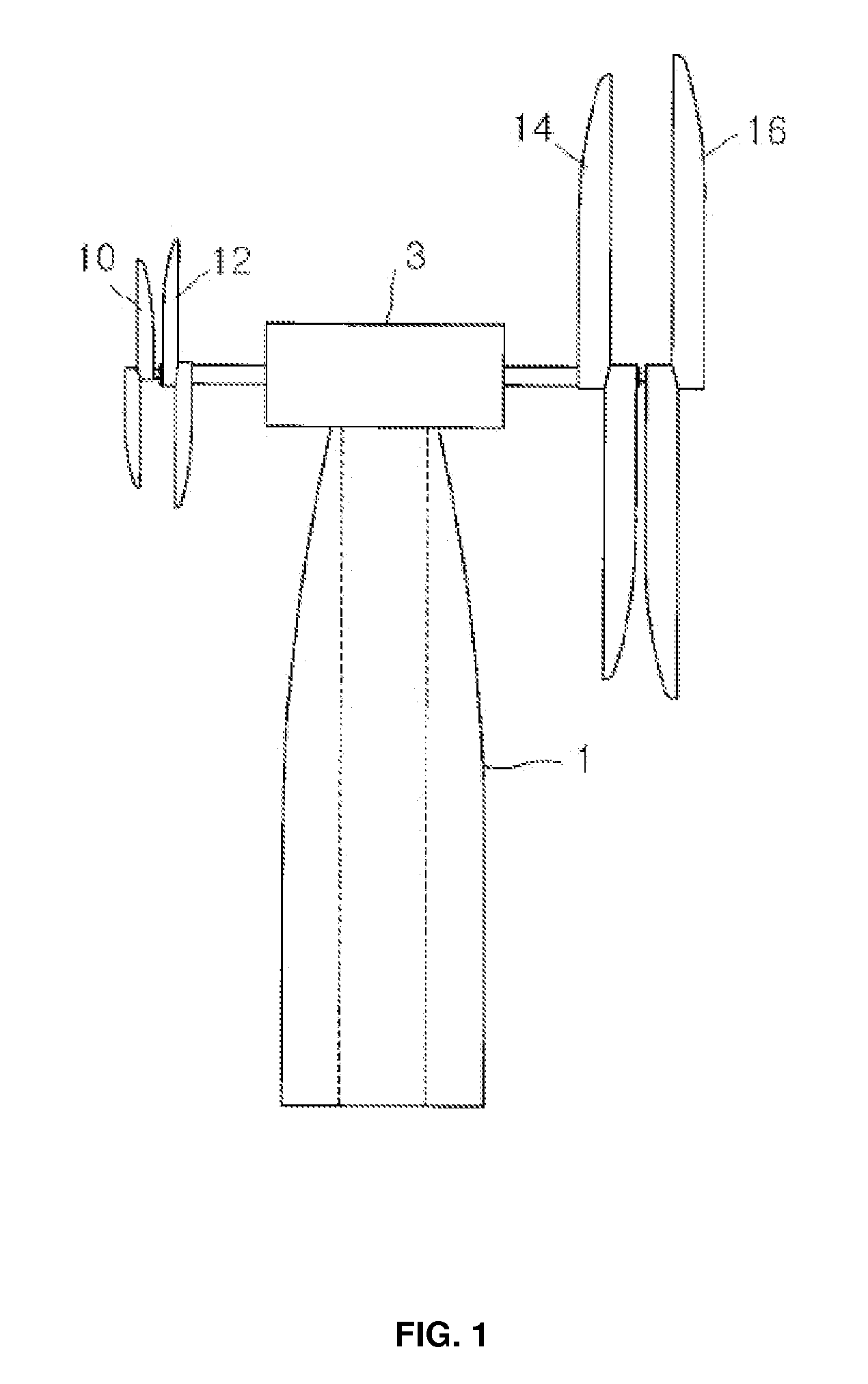
[0017]FIG. 1 is a schematic view illustrating a windmill-type electric power generation system according to the present invention.

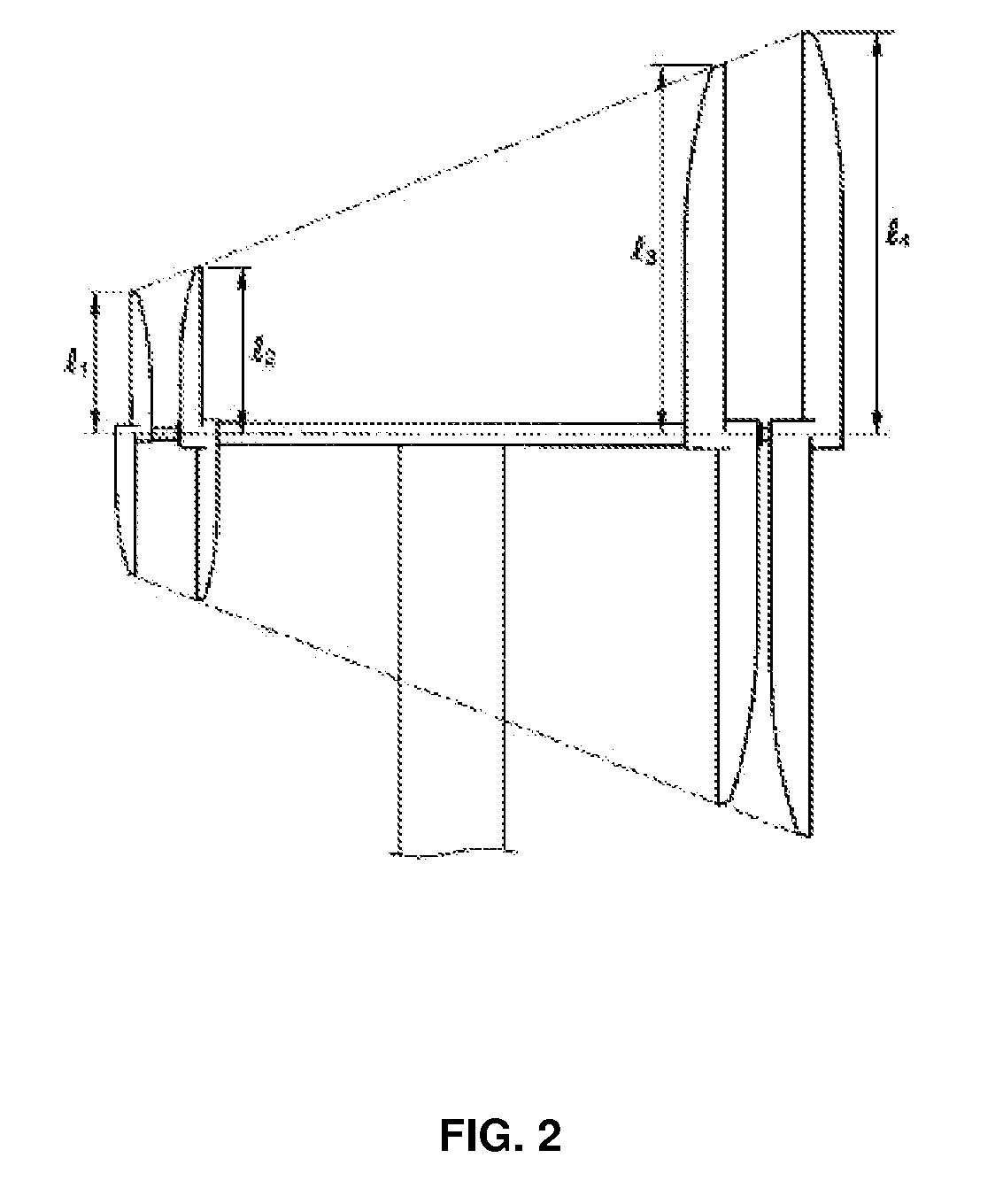
[0018]Referring to FIG. 1, a housing 3 is mounted at the upper end of a supporting post, and rotary shafts, on which a plurality of rotary blade units are securely mounted, and power transmission mechanisms are mounted in the housing 3 such that the rotary blade units can be rotated in the blowing direction of wind. As shown in FIG. 1, the windmill-type electric power generation system according to the present invention includes two front rotary blade units 10 and 12, which are disposed in front of the housing 3, and two rear rotary blade units 14 and 16, which are disposed in the rear of the housing 3. These four rotary blade units 10, 12, 14, and 16 have different lengths. Specifically, the length of the second rotary blade ...


PUM


Abstract

Disclosed herein is a windmill-type electric generation system that generates a large rotating force even from a small amount of wind. The electric generation system includes four rotary blade units (10, 12, 14, 16) mounted on opposite ends of corresponding rotary shafts in pairs, a first power transmission mechanism for transmitting the rotating movement of the blade units (12, 14) to an armature (110) of an electric generator (100), a second power transmission mechanism for transmitting the rotating movement of the blade units (10, 16) to a magnetic pole (120) of the electric generator (100), and the electric generator (100) for generating electricity through the rotation of the armature (110) and the magnetic pole (120) in the opposite directions, which is accomplished by the rotating movement of the blade units (10, 12, 14, 16) transmitted to the armature (110) and the magnetic pole (120) by the power transmission mechanisms.

Description

REFERENCE TO RELATED APPLICATIONS[0001]This is a continuation of pending International Patent Application PCT / KR2006 / 000999 filed on Mar. 20, 2006, which designates the United States and claims priority of Korean Patent Application No. 10-2005-0023968 filed on Mar. 23, 2005.FIELD OF THE INVENTION[0002]The present invention relates to a windmill-type electric generation system, and, more particularly, to a windmill-type electric generation system wherein four rotary blade units having different lengths are provided to generate a large rotating force even from a small amount of wind, and a magnetic pole and an armature of an electric generator are rotated in opposite directions.BACKGROUND OF THE INVENTION[0003]Various wind power generation systems, i.e., windmill-type electric generation systems have been proposed. One of the conventional windmill-type electric generation systems is described in the specification of Korean Patent Application No. 2000-76789, which is related to the pre...

Claims


Application Information

Patent Timeline
Patent Type & Authority Applications(United States)
IPC IPC(8): F03D1/02
CPCF03D1/025F03D7/0204F03D11/02Y02E10/723F05B2260/4031Y02E10/722F05B2250/311F03D15/00F03D15/10F03D9/25Y02E10/72
Inventor HONG, GU DUCK
Owner HONG GU DUCK
Learn More