Fault tolerant permanent magnet machine

a permanent magnet machine and fault-tolerant technology, applied in the direction of rotating magnets, synchronous machines with stationary armatures, windings, etc., can solve the problems of reducing the ability to properly operate the engine, affecting the reliability affecting the fault tolerance of the pm generator, so as to increase the size and weight of the device and increase the cost of the pm machin

Inactive Publication Date: 2010-04-15
GENERAL ELECTRIC CO
View PDF35 Cites 27 Cited by
  • Summary
  • Abstract
  • Description
  • Claims
  • Application Information

AI Technical Summary

Benefits of technology

[0007]Further, fault-tolerant systems currently used in PM machines substantially increase the size and weight of these devices limiting the scope of applications in which such

Problems solved by technology

When operating an aircraft engine at relatively low power levels, e.g., while idly descending from altitude, extracting this additional electrical power from the engine mechanical power may reduce the ability to operate the engine properly.
The LP engine spool provides an alternate source of power transfer, however, the relatively lower speed of the LP engine spool typically requires the use of a gearbox, as slow-speed electrical generators are often larger than similarly rated electrical generators operating at higher speeds.
However, aviation applications require fault tolerance, and as discussed below, PM machines can experience faults under certain circumstances and existing techniques for fault tolerant PM generators suffer from drawbacks, such as increased size and weight.
Consequently, should an electrical device having a PM experien

Method used


Image

  • Fault tolerant permanent magnet machine
  • Fault tolerant permanent magnet machine
  • Fault tolerant permanent magnet machine

Examples


Embodiment Construction

[0021]As discussed in detail below, embodiments of the invention are directed to fault tolerant permanent magnet machines. As used herein, the term ‘fault tolerant’ refers to magnetic and physical decoupling between various machine coils / phases while reducing noise, torque ripple, and harmonic flux components. In addition the improved fault tolerant PM machines has high power density and efficiency. Furthermore, embodiments of the machine configuration increase inductance in order to reduce fault current and provide desirable voltage regulation.

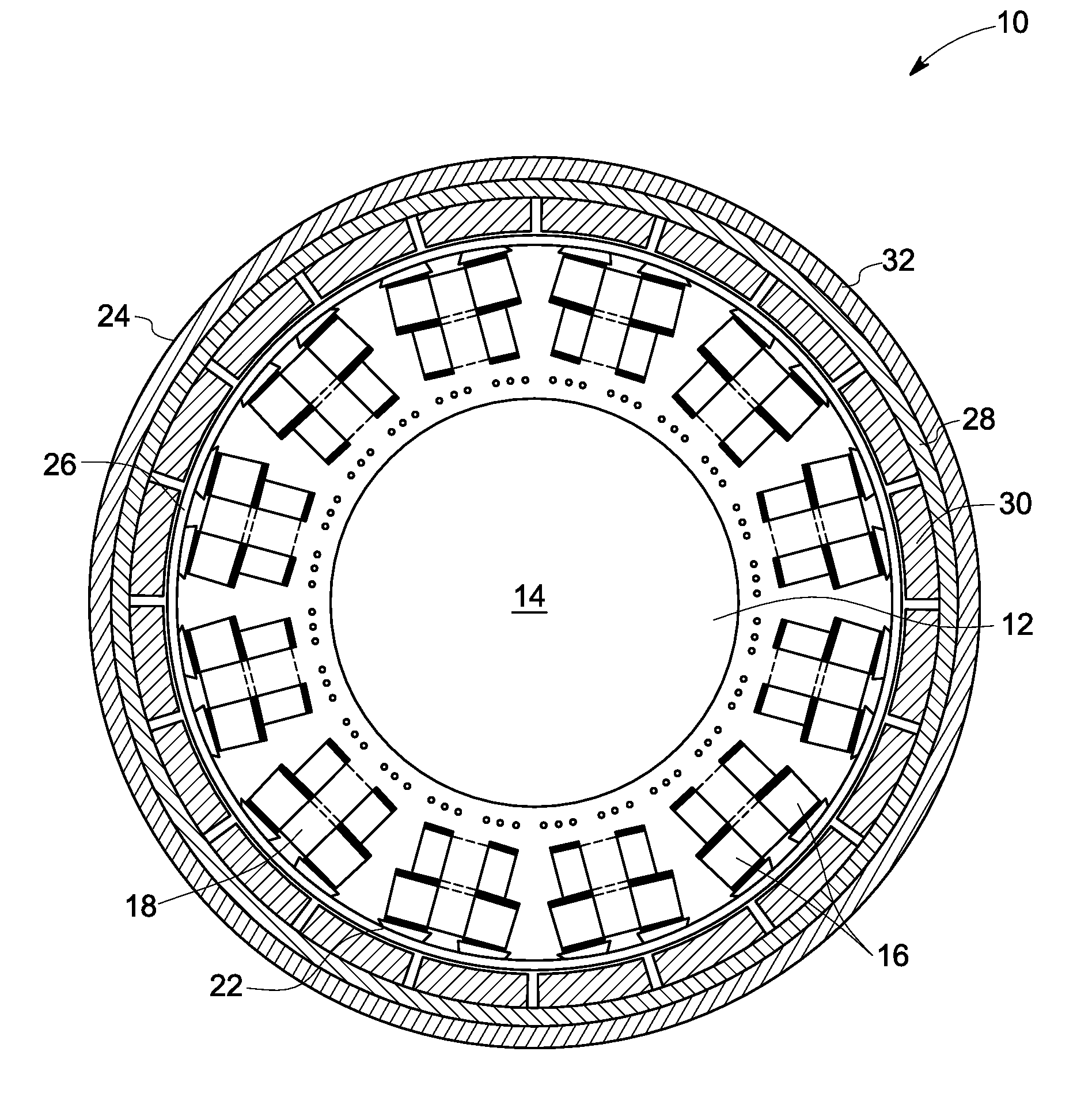
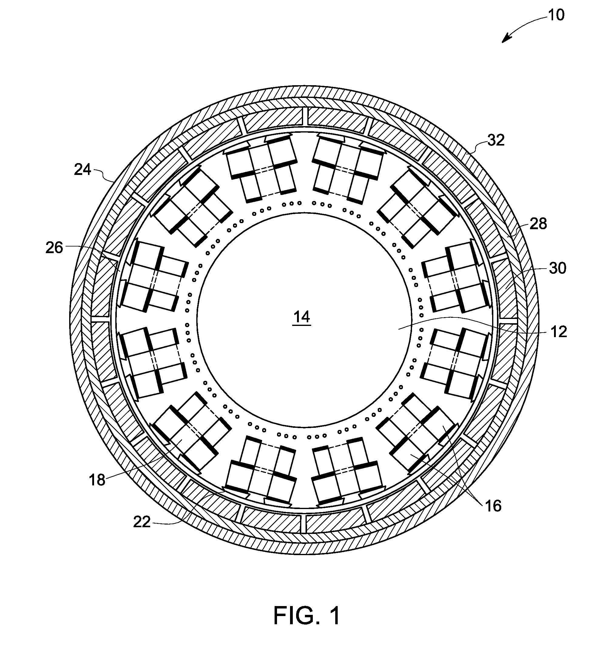
[0022]FIG. 1 is a diagrammatic illustration of a permanent magnet (PM) machine 10. The PM machine 10 includes a stator 12 having a stator core 14. The stator core 14 defines multiple step-shaped stator slots 16 including multiple fractional-slot concentrated windings 18 wound within the step-shaped stator slots 16. The fractional-slot concentrated windings provide magnetic and physical decoupling between various phases and coils of the PM mac...


PUM

PropertyMeasurementUnit
Poweraaaaaaaaaa
Poweraaaaaaaaaa
Electrical inductanceaaaaaaaaaa

Abstract

A PM machine is provided. The PM machine includes a stator including a stator core, wherein the stator core defines multiple step-shaped stator slots. The stator includes multiple fractional-slot concentrated windings wound within the step-shaped stator slots. The stator also includes at least one slot wedge configured to close an opening of a respective one of the step-shaped stator slots, wherein the slot wedge is further configured to adjust the leakage inductance in the PM machine. The PM machine also includes a rotor having a rotor core and disposed outside and concentric with the stator, wherein the rotor core includes a laminated back iron structure disposed around multiple axially-segmented magnets.

Description

CROSS REFERENCE TO RELATED APPLICATIONS[0001]This application is related to the following co-pending United States patent application Serial No. {Attorney Docket No. 228153-2}, entitled “THERMAL MANAGEMENT IN A FAULT TOLERANT PERMANENT MAGNET MACHINE” assigned to the same assignee as this application and filed herewith, the entirety of which is incorporated by reference herein.BACKGROUND[0002]The invention relates generally to permanent magnet (PM) machines, such as electric generators and / or electric motors. Particularly, this invention relates to fault tolerant PM machines.[0003]Many new aircraft systems are designed to accommodate electrical loads that are greater than those on current aircraft systems. The electrical system specifications of commercial airliner designs currently being developed may demand up to twice the electrical power of current commercial airliners. This increased electrical power demand must be derived from mechanical power extracted from the engines that p...

Claims


Application Information

Patent Timeline
IPC IPC(8): H02K21/22H02K15/06H02K3/493
CPCH02K1/146H02K1/165Y10T29/49009H02K3/40H02K21/22H02K3/24
Inventor EL-REFAIE, AYMAN MOHAMED FAWZIKERN, JOHN MICHAELSHAH, MANOJ RAMPRASADGERSTLER, WILLIAM DWIGHTVANDAM, JEREMY DANIEL
Owner GENERAL ELECTRIC CO
Why Eureka
Try Eureka