Zoom lens system, interchangeable lens apparatus and camera system

a technology of zoom lens and interchangeable lens, which is applied in the field of zoom lens system, can solve the problems of excessively large outer diameter of the lens barrel and the feeling of unease of the person who takes an image, and achieve the effect of suppressing the change in image magnification

Active Publication Date: 2010-04-15
PANASONIC CORP
View PDF8 Cites 23 Cited by
  • Summary
  • Abstract
  • Description
  • Claims
  • Application Information

AI Technical Summary

Benefits of technology

[0022]According to the present invention, a zoom lens system that includes a compactly constructed focusing lens unit and that has a suppressed change in the image magnification at the time of movement of a focusing lens unit, an interchangeable lens apparatus and a camera system that employ this zoom lens system can be provided.
[0023]These and other objects, features, aspects and effects of the present invention will become clearer on the basis of the following detailed description with reference to the accompanying drawings.

Problems solved by technology

This causes a problem that the lens barrel has an excessively large outer diameter.
Then, when a large change in the image taking magnification is generated in association with wobbling, the person who takes an image feels uneasiness.

Method used


Image

  • Zoom lens system, interchangeable lens apparatus and camera system
  • Zoom lens system, interchangeable lens apparatus and camera system
  • Zoom lens system, interchangeable lens apparatus and camera system

Examples


embodiment 1

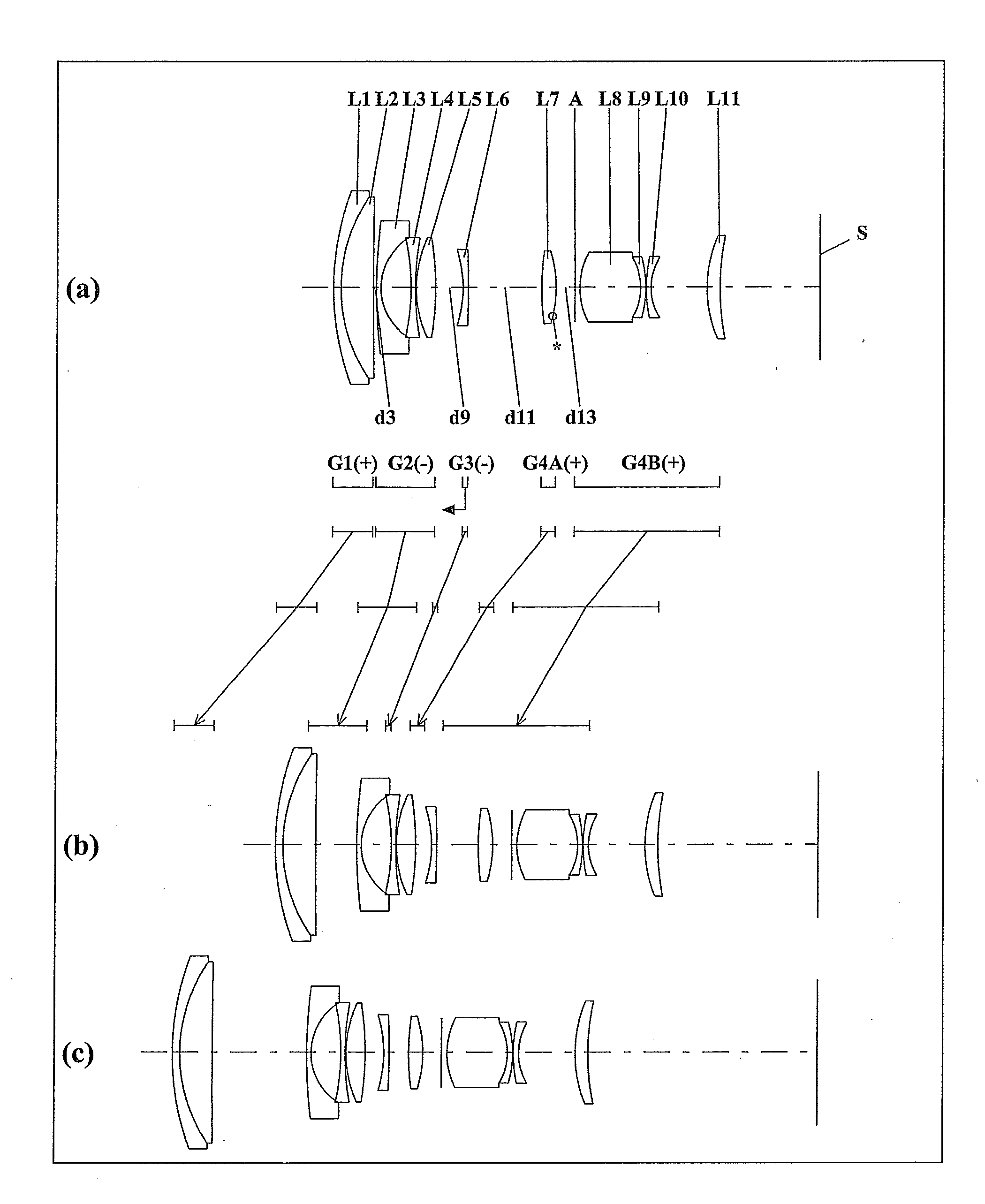
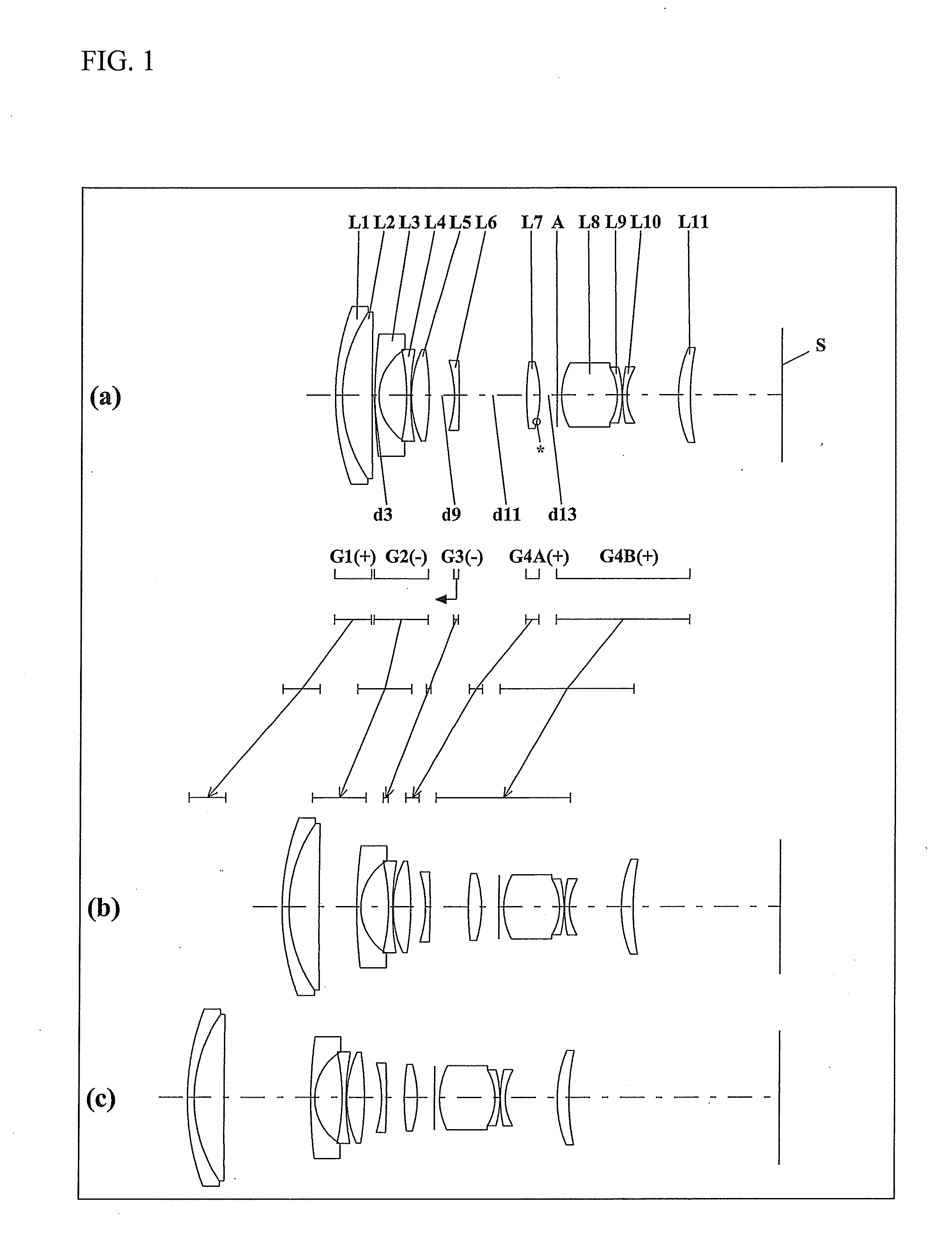
[0110]The zoom lens system according to Embodiment 1, in order from the object side to the image side, comprises a first lens unit G1 having positive optical power, a second lens unit G2 having negative optical power, a third lens unit G3 having negative optical power, a lens unit G4A having positive optical power, and a lens unit G4B having positive optical power. The lens units G4A and G4B constitute a fourth lens unit G4.

[0111]The first lens unit G1, in order from the object side to the image side, comprises: a negative meniscus first lens element L1 with the convex surface facing the object side; and a positive meniscus second lens element L2 with the convex surface facing the object side. The first lens element L1 and the second lens element L2 are cemented with each other.

[0112]The second lens unit G2, in order from the object side to the image side, comprises: a negative meniscus third lens element L3 with the convex surface facing the object side; a bi-concave fourth lens el...

embodiment 2

[0119]The zoom lens system according to Embodiment 2, in order from the object side to the image side, comprises a first lens unit G1 having positive optical power, a second lens unit G2 having negative optical power, a third lens unit G3 having negative optical power, a lens unit G4A having positive optical power, and a lens unit G4B having positive optical power. The lens units G4A and G4B constitute a fourth lens unit G4.

[0120]The first lens unit G1, in order from the object side to the image side, comprises: a negative meniscus first lens element L1 with the convex surface facing the object side; and a positive meniscus second lens element L2 with the convex surface facing the object side. The first lens element L1 and the second lens element L2 are cemented with each other with an adhesive layer in between.

[0121]The second lens unit G2, in order from the object side to the image side, comprises: a negative meniscus third lens element L3 with the convex surface facing the object...

embodiment 3

[0128]The zoom lens system according to Embodiment 3, in order from the object side to the image side, comprises a first lens unit G1 having positive optical power, a second lens unit G2 having negative optical power, a third lens unit G3 having negative optical power, a lens unit G4A having positive optical power, and a lens unit G4B having positive optical power. The lens units G4A and G4B constitute a fourth lens unit G4.

[0129]The first lens unit G1, in order from the object side to the image side, comprises: a negative meniscus first lens element L1 with the convex surface facing the object side; and a positive meniscus second lens element L2 with the convex surface facing the object side. The first lens element L1 and the second lens element L2 are cemented with each other with an adhesive layer in between.

[0130]The second lens unit G2, in order from the object side to the image side, comprises: a negative meniscus third lens element L3 with the convex surface facing the object...


PUM


Abstract

A zoom lens system is provided that includes a compactly constructed focusing lens unit and that has a suppressed change in the image magnification at the time of movement of a focusing lens unit. The zoom lens system according to the present invention comprises: a positive lens unit that is arranged on an object side relative to the aperture diaphragm; a negative lens unit that is arranged on an image side relative to the positive lens unit and on an object side relative to the aperture diaphragm; and a focusing lens unit that is arranged in an optical path between the negative lens unit and the aperture diaphragm. The zoom lens system satisfies the condition (4): 1.20<βNTNW<4.50 (here, fT/fW>3.0, βNTNW): a composite focal length of the focusing lens unit and the negative lens unit in an infinity in-focus condition at a telephoto (wide-angle) limit when the focusing lens unit has negative optical power, or a lateral magnification of the negative lens unit at a telephoto limit in an infinity in-focus condition when the focusing lens unit has positive optical power, fT: a focal length of the entire system at a telephoto limit, fW: a focal length of the entire system at a wide-angle limit.

Description

BACKGROUND OF THE INVENTION[0001]1. Field of the Invention[0002]The present invention relates to a zoom lens system and, in particular, to a zoom lens system suitable for an imaging lens system employed in an interchangeable lens apparatus in a so-called interchangeable-lens type digital camera system (simply referred to as a “camera system”, in some cases hereinafter). Further, the present invention relates to an interchangeable lens apparatus and a camera system that employ this zoom lens system.[0003]2. Description of the Background Art[0004]In recent years, interchangeable-lens type digital camera systems are spreading rapidly. Such an interchangeable-lens type digital camera system has: a camera body employing an image sensor composed of a CCD (Charge Coupled Device), a CMOS (Complementary Metal-Oxide Semiconductor) or the like; and an interchangeable lens apparatus employing an imaging lens system for forming an optical image on the light receiving plane of the image sensor. Z...

Claims


Application Information

Patent Timeline
Patent Type & Authority Applications(United States)
IPC IPC(8): H04N5/232G02B15/20
CPCG02B27/646G02B15/17G02B15/144109G02B15/1451
Inventor MIYAZAKI, KYOICHIYAMADA, KATSUIMAOKA, TAKUYASAMPEI, MASAKI
Owner PANASONIC CORP
Why Eureka
Try Eureka