
Timepiece gear train

Inactive Publication Date: 2010-04-15
MONTRES BREGUET +1
View PDF15 Cites 5 Cited by
  • Summary
  • Abstract
  • Description
  • Claims
  • Application Information

AI Technical Summary

Benefits of technology

[0008]It is an object of the present invention to improve a timepiece gear train so as to substantially overcome the aforementioned drawbacks of the gears usually used in this field, by making transmission of torque and / or velocity more uniform, without weakening the teeth and excessively complicating manufacture and assembly.
[0010]Because of this arrangement, the N toothed rings of each toothing act one after the other. For the same toothing module, the length of the path of contact is divided by N and this path remains confined in proximity to the centre line, i.e. in the area where it is easier for the profile of each tooth to be optimal and where the gear conditions are most favourable, in particular while exhibiting a low radii variation during a tooth lead. As a result, the torque and velocity ratios are much more uniform than with simple toothings, even with the tooth profiles usually used in watch making. By preventing contact between teeth in areas far from the centre line, where the profile is not optimum and hertzians pressures are higher, the gear has a better yield and is less subject to wear. Thus, the advantages of large module toothings are combined with those of toothings with a large number of teeth, while avoiding, to a great extent, their specific drawbacks. Moreover, the additional manufacturing cost is limited to multiplying some elements, without making them more difficult to manufacture.

Problems solved by technology

Moreover, the additional manufacturing cost is limited to multiplying some elements, without making them more difficult to manufacture.

Method used


Image

  • Timepiece gear train
  • Timepiece gear train
  • Timepiece gear train

Examples


Embodiment Construction

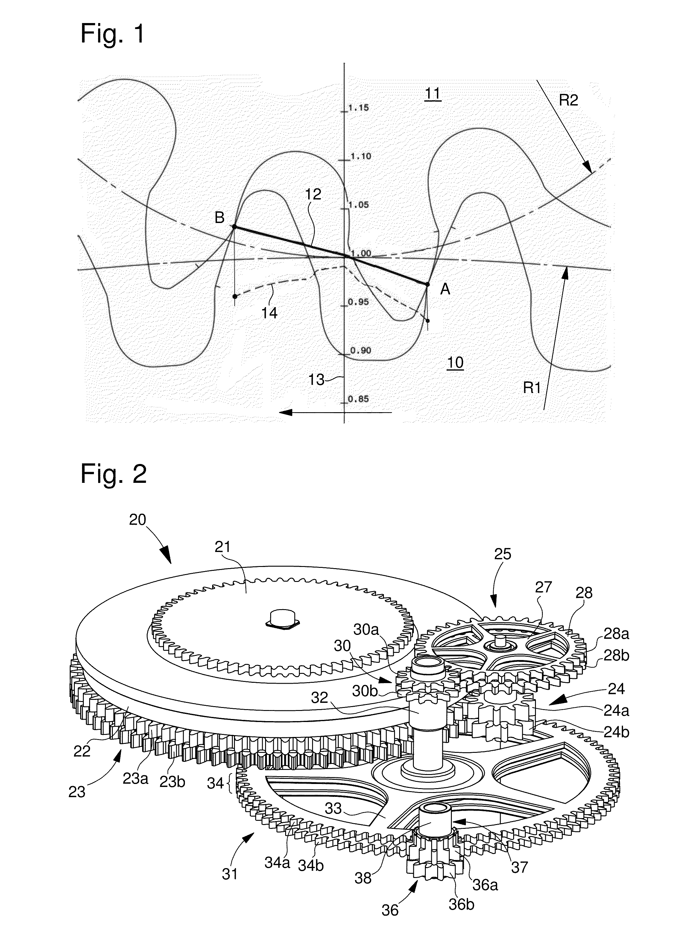
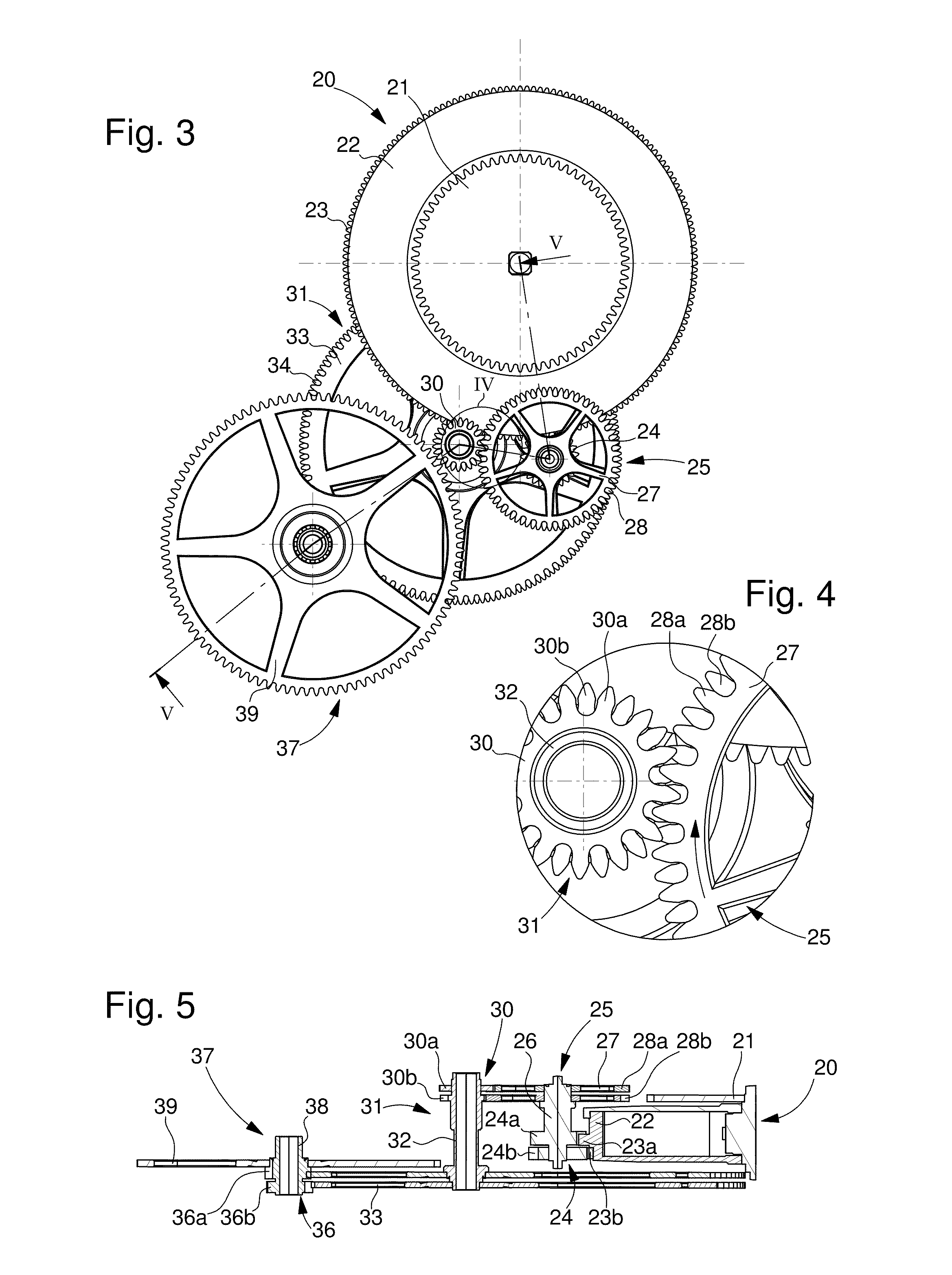
[0019]FIGS. 2 to 5 show the barrel spring 20 of a watch movement, including a ratchet 21 and a rotating drum 22 whose peripheral wall is fitted with a straight toothing 23 that meshes on a pinion 24 of an intermediate wheel set 25. Wheel set 25 also has an arbour 26 and an intermediate wheel 27. Toothing 28 of the intermediate wheel meshes on a pinion 30 of a centre wheel set 31 that further includes a tubular arbour 32 and a centre wheel 33. Toothing 34 of the centre wheel meshes on a pinion 36 of a third wheel set 37 that further includes a tubular arbour 38 and third wheel 39, which is omitted from FIG. 2 to make the drawing more clear. These wheel sets form the upstream part of the going train of the watch, the downstream part of which transmits the movement of the third wheel 39 to the regulating member. In order to make the drawings clear, the elements that support the rotating wheel sets described have not been shown.

[0020]According to the principle of the invention explained...


PUM


Abstract

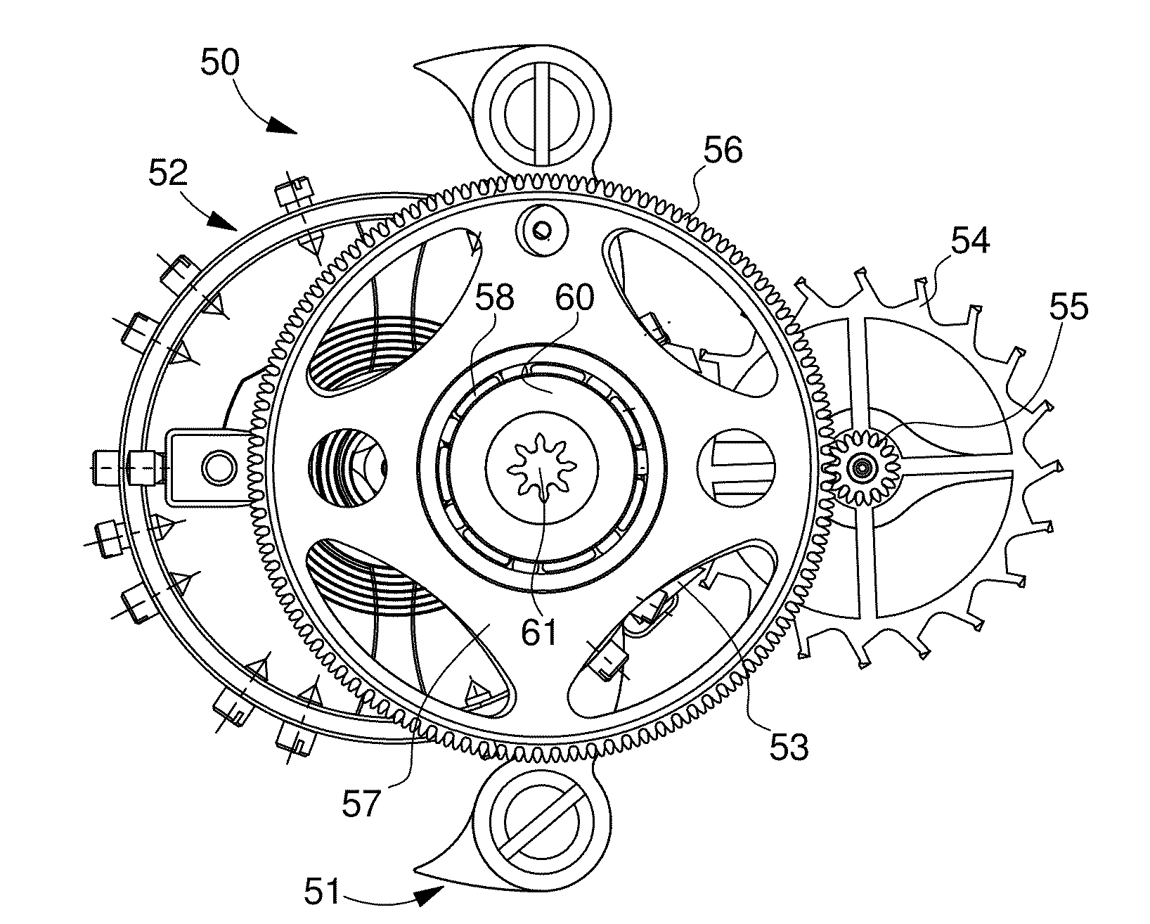
The invention concerns a timepiece gear train including at least one pair of circular toothed elements (25, 31) with parallel axes, the elements being provided with respectively toothings that are meshed with each other so that one (25) of the elements drives the other. In order to improve transmission conditions within the gear without reducing the toothing module, the corresponding toothings of each of the two elements are multiple, each of them being formed of N coaxial, toothed rings (28a, 28b; 30a, 30b) angularly shifted relative to each other by a fraction of a pitch of the toothing. In the simplest version, each of the toothings is double (N=2), the two rings being angularly shifted by a half-pitch. The invention prevents gearing in areas located relatively far from the line connecting the centres of the toothed elements, thus reducing torque and velocity variations during the lead of a tooth. Applications are envisaged in particular in a going train, a display train and a rotating escapement, such as a tourbillon.

Description

BACKGROUND OF THE INVENTION[0001]The present invention concerns a timepiece gear train including at least one pair of circular, toothed elements, with parallel axes, wherein the toothed elements are provided with respective toothings that mesh with each other. The invention applies in particular to pairs of rotating wheel sets of the going train, which connects the drive motor of a mechanical timepiece movement to the regulating member, in particular to the escape wheel set thereof. However, the invention may find other applications in watch making, for example in a display train.[0002]In gears in general and in a gear with straight teeth in particular, the point of contact between the combined profiles of the flanks of the two teeth that are touching moves radially during the arc of action or lead of a tooth, by rising towards the head of the driving tooth. This phenomenon is illustrated schematically in the annexed FIG. 1, which shows the gearing of a driving wheel 10 with eighty-...

Claims


Application Information

Patent Timeline
IPC IPC(8): G04B19/02G04B15/00
CPCF16H55/17G04B13/02G04B35/00G04B19/02G04B17/285
Inventor GOELLER, ERICCALABRESE, VINCENT
Owner MONTRES BREGUET
Learn More