Device for determining the position and/or the transverse dimension of a drill hole in a presentation lens for rimless eyeglasses

a technology for ophthalmic lenses and drill holes, which is applied in the field of drilling holes in the presentation lens for rimless eyeglasses, can solve the problems of degrading the performance of optical correction, affecting the performance of the optical correction, and affecting the quality of the lens

Active Publication Date: 2010-04-15
ESSILOR INT CIE GEN DOPTIQUE
View PDF10 Cites 14 Cited by
  • Summary
  • Abstract
  • Description
  • Claims
  • Application Information

AI Technical Summary

Benefits of technology

[0040]Then, and advantageously, said means for defining the position of center of the orifice of the drill hole opening into said face calculate a first correction as a function of the refractive index and / or the thickness of the presentation lens. This enables the image acquisition errors that result from prismatic deflections generated by the presentation lens onto its own image to be corrected.

Problems solved by technology

However, in particular for lenses that are greatly curved, it is observed that an often significant error exists between the position of the drill hole drilled in the corrective lens and the real position and dimension of the drill hole in the presentation lens.
This error in the positioning and the dimension of the hole leads to difficulties in mounting the lens onto the temples and the nose bridge and may even, in some circumstances, end up with mounting being impossible or of poor quality, or may even oblige the optician to perform a reworking operation that is time consuming and that requires expert knowledge.
Further, the corrective lens may, as a result, be poorly positioned in front of the eye of the wearer, thereby degrading its performance in optical correction.

Method used


Image

  • Device for determining the position and/or the transverse dimension of a drill hole in a presentation lens for rimless eyeglasses
  • Device for determining the position and/or the transverse dimension of a drill hole in a presentation lens for rimless eyeglasses
  • Device for determining the position and/or the transverse dimension of a drill hole in a presentation lens for rimless eyeglasses

Examples


Embodiment Construction

[0047]The description below, with reference to the accompanying drawings, given by way of non-limiting example, makes it well understood what the invention consists in, and how it can be reduced to practice.

[0048]In the accompanying drawings

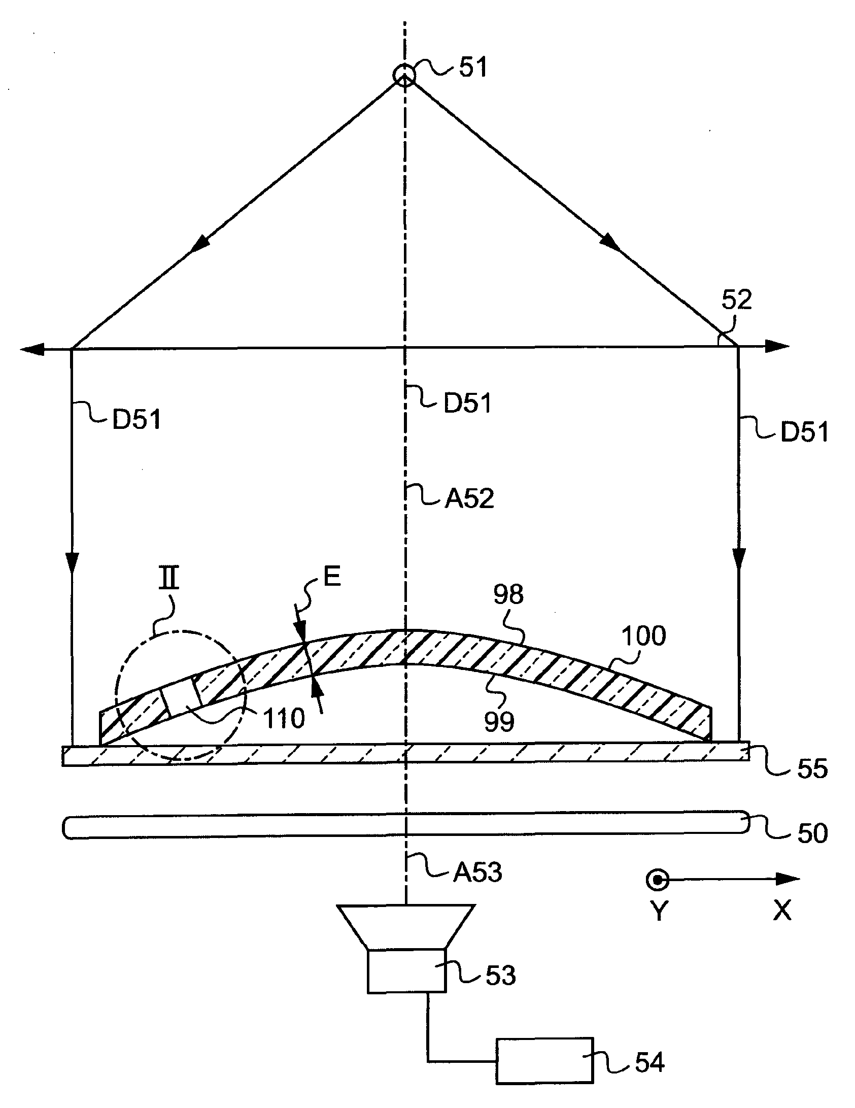
[0049]FIG. 1 is a diagrammatic view in axial section of an acquisition device for acquiring the position of the drill holes of a presentation lens in a first implementation of the invention;

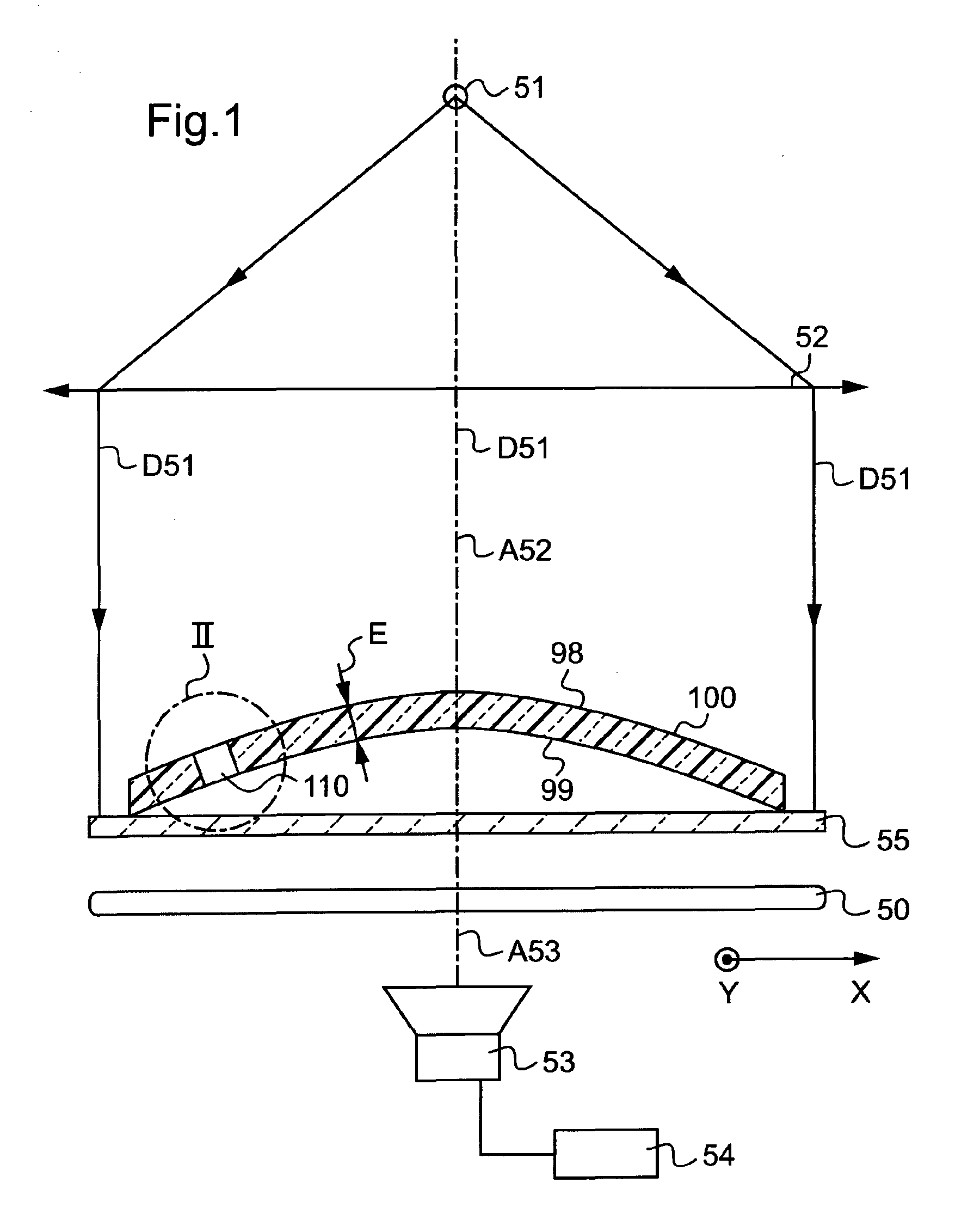
[0050]FIG. 2 is a combined view, with a top portion showing in axial section the drill hole of the presentation lens of FIG. 1 and a bottom portion showing, in a transverse plane, the overall image of the shadow of the drill hole projected onto the acquisition means, some of the points of the image being used for calculating the position of the drill hole in a first method;

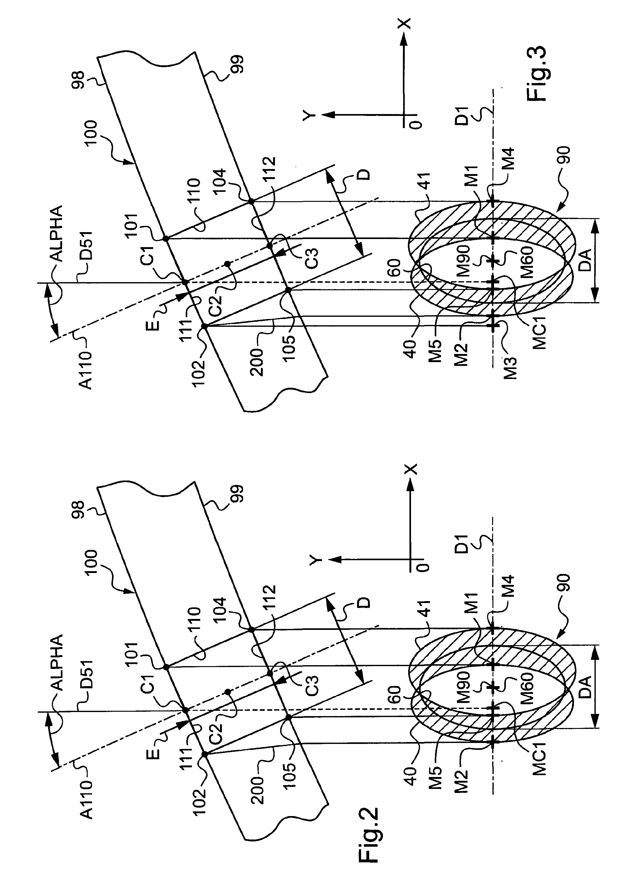
[0051]FIG. 3 is a combined view similar to FIG. 2 on which the position of an additional point has been added in order to calculate the position of the drill hole in a variant of the first m...


PUM


Abstract

The device includes: bearing element (55) for the lens (100); element (53) for acquiring a global image (90) of the drill hole (110) of the lens (100) in a lighting direction (D51, A52), or image acquisition direction (A53); element (54) for processing the image when the lens is carried by the carrier element (55). The processing element (54) designed for determining, from the global image of the drill hole (110) the position of center (C1) of the opening of the drill hole (110) that gives onto one of the faces (98) of the lens (100) and/or the transverse dimension of the opening of the drill hole (110) that corresponds to the desired transverse dimension (D).

Description

TECHNICAL FIELD OF THE INVENTION[0001]The present invention relates in a general manner to mounting ophthalmic lenses of a pair of eyeglasses in a rimless type frame, and more particularly it relates to a device for determining the position and / or the transverse dimension of a drill hole of a presentation lens (that is used as a model) with a view to drilling, at said position and / or said transverse dimension, an unmounted lens that is to be assembled with a rimless eyeglass frame.TECHNOLOGICAL BACKGROUND[0002]When an eyeglass frame is of the rimless type, the shaping of each of the corrective lenses intended to be joined to the frame is followed by drilling each lens appropriately so as to enable the temples and the nose bridge of the rimless frame to be fastened thereon. The drilling may be performed with an edger or with a separate drilling machine by means of a drill bit.[0003]Most often, the following drilling method is implemented. First, the future wearer chooses the desired ...

Claims


Application Information

Patent Timeline
Patent Type & Authority Applications(United States)
IPC IPC(8): G06K9/00G06V30/224
CPCB24B13/0055B24B9/146
Inventor PINAULT, PHILIPPE
Owner ESSILOR INT CIE GEN DOPTIQUE
Why Eureka
Try Eureka