Drill bit for drilling having at least two cutting edges, each with two cutting portions and a non-cutting portion between the two cutting portions

a drilling bit and cutting edge technology, applied in the direction of twisting drills, manufacturing tools, wood boring tools, etc., can solve the problems of increasing the free space of drill bits, affecting so as to ensure the accuracy of drilling holes, prevent, restrict, and/or minimize the effect of chips

Active Publication Date: 2010-04-15
KENNAMETAL INC
View PDF10 Cites 45 Cited by
  • Summary
  • Abstract
  • Description
  • Claims
  • Application Information

AI Technical Summary

Benefits of technology

[0013]As a result of this specific configuration, the chips which are generated are therefore split, in the case of a continuous cutting edge divided merely into different portions, into two smaller chip parts, thus allowing chips to be removed reliably and without difficulty via the chip groove. The cutting edge therefore runs as a whole on the end face of the, for example conical, bit without axial offset, the inactive cutting portion joining together the two active cutting portions. The term “smaller chip parts” refers in this case to the fact that the width, defined by the length of the cutting edge, of the chip is size-reduced. The chip is therefore divided in the radial direction from the outset. In the axial direction, the individual chip parts are in one possible embodiment not broken, i.e. long-chip partial chips are formed. It is therefore crucial that the cutting edge geometry leads to the formation of two partial chips directly on the cutting edge.
[0032]For reliable running side-by-side of the two partial chips, provision is in one possible embodiment also made for the two partial chip grooves to have different angles of twist, wherein in one possible embodiment the outer partial chip groove has a larger angle of twist than the inner partial chip groove. The term “angle of twist” refers in this case generally to the orientation of the respective partial chip groove based on the drill longitudinal direction.

Problems solved by technology

Thus, the problem often occurs that the machining process leads to the formation of chips which are embodied in a substantially helical manner and some of which take up more free space than the free space provided by the chip groove.
This may lead to the chips becoming stuck within the chip groove, so that discharge is no longer reliably essentially ensured or promoted.
There is also the risk of chips passing between the drill circumference and the drill wall and becoming stuck there; this leads to damage to the drill wall and to imprecise drill hole geometry and also to greatly increased stressing of the drill tool.
The problem of sufficiently safe removal of chips is encountered for example in long-chipping materials, such as for example high-grade stainless steel, in which very long chips are formed during the machining process.
If two separated partial chip grooves were dispensed with, the short-chip inner partial chip would merge with the long-chip outer partial chip, so that there is the risk of the formation of a snarl chip which is problematic to remove.
As a result, the design measures are restricted merely to the region of the bit and it is not necessary or desired to form the two partial chip grooves over the entire length of the drill.

Method used


Image

  • Drill bit for drilling having at least two cutting edges, each with two cutting portions and a non-cutting portion between the two cutting portions
  • Drill bit for drilling having at least two cutting edges, each with two cutting portions and a non-cutting portion between the two cutting portions
  • Drill bit for drilling having at least two cutting edges, each with two cutting portions and a non-cutting portion between the two cutting portions

Examples


Embodiment Construction

[0047]In the figures, equivalent parts are provided with the same reference numerals.

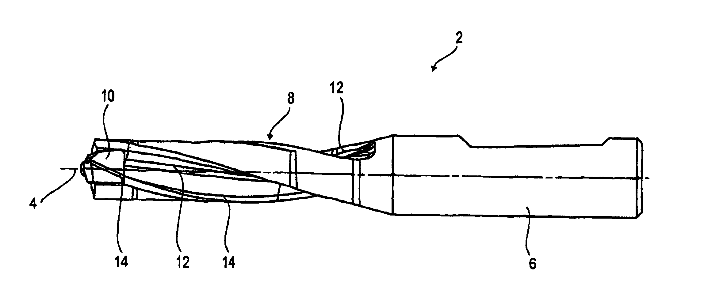
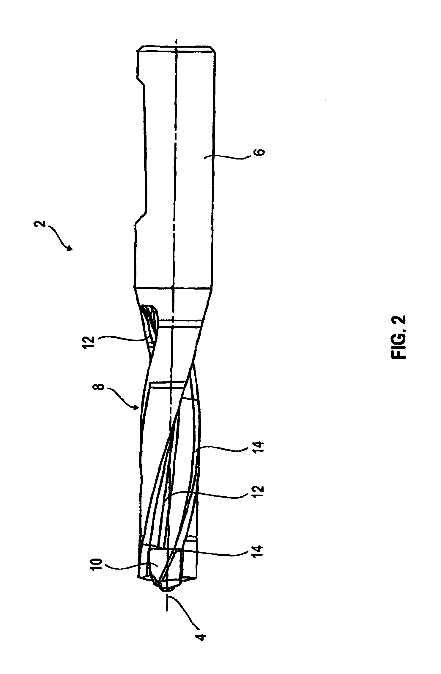
[0048]As may be seen from FIG. 2, the twist drill 2 shown therein extends in the longitudinal direction along a drill center axis 4. It has at its trailing end a shank portion 6 with which it is clamped into a suitable machining device. The shank portion 6 is adjoined by a drill body 8 having at its front end a bit 10. The twist drill 2 shown comprises two helically running chip grooves 12 extending into the bit 10. Coolant holes, which issue at the front end or close to the tip of the bit 10, are conventionally passed through the entire twist drill 2. Along the chip groove 12 there runs in the drill longitudinal direction a respective secondary cutting edge 14 which is therefore also embodied so as to run helically.

[0049]In one possible embodiment, the bit 10 is embodied as an exchangeable, separate part which is fastened in the drill body 8 in a clamping manner. The twist drill 2 shown in FIG. 2 i...


PUM

PropertyMeasurementUnit
cutting angleaaaaaaaaaa
chip angleaaaaaaaaaa
angleaaaaaaaaaa

Abstract

A drill bit for drilling having at least two cutting edges, each with two cutting portions and a non-cutting portion between the two cutting portions. The abstract of the disclosure is submitted herewith as required by 37 C.F.R. §1.72(b). As stated in 37 C.F.R. §1.72(b): A brief abstract of the technical disclosure in the specification must commence on a separate sheet, preferably following the claims, under the heading “Abstract of the Disclosure.” The purpose of the abstract is to enable the Patent and Trademark Office and the public generally to determine quickly from a cursory inspection the nature and gist of the technical disclosure. The abstract shall not be used for interpreting the scope of the claims. Therefore, any statements made relating to the abstract are not intended to limit the claims in any manner and should not be interpreted as limiting the claims in any manner.

Description

CONTINUING APPLICATION DATA[0001]This application is a Continuation-In-Part application of International Patent Application No. PCT / EP2007 / 008595, filed on Oct. 4, 2007, which claims priority from Federal Republic of Germany Patent Application No. 10 2006 049 096.7, filed on Oct. 13, 2006, and Federal Republic of Germany Patent Application No. 10 2007 031 440.1, filed on Jul. 5, 2007. International Patent Application No. PCT / EP2007 / 008595 was pending as of the filing date of this application. The United States was an elected state in International Patent Application No. PCT / EP2007 / 008595.BACKGROUND[0002]1. Technical Field[0003]The present application relates to a drill bit for drilling having at least two cutting edges, each with two cutting portions and a non-cutting portion between the two cutting portions. The present application further relates to a bit for a drill tool extending along a drill center axis in the drill longitudinal direction and having an outwardly extending cutt...

Claims


Application Information

Patent Timeline
Patent Type & Authority Applications(United States)
IPC IPC(8): B23B51/02
CPCB23B51/02B23B2251/14Y10T408/9097B23B2251/406B23B2251/18B23B51/00
Inventor BORSCHERT, BERNHARDKRENZER, ULLRICHKAUPER, HERBERT
Owner KENNAMETAL INC
Why Eureka
Try Eureka