Continuously variable transmission

a transmission and continuous variable technology, applied in the direction of machines/engines, road transportation, gearing, etc., can solve the problems of oversizing of accessories, wasting energy during operation, and accessory speed not operating within the maximum efficiency speed rang

Active Publication Date: 2010-04-15
FALLBROOK INTPROP COMPANY
View PDF50 Cites 128 Cited by
  • Summary
  • Abstract
  • Description
  • Claims
  • Application Information

AI Technical Summary

Benefits of technology

[0007]The systems and methods herein described have several features, no single one of which is solely responsible for its desirable attributes. Without limiting the scope as expressed by the claims that follow, its more prominent features will now be discussed briefly.

Problems solved by technology

However, it is often the case that the optimum operating speed of the driven device is not directly proportional to the optimum operating speed of the power source.
The result of such system configuration is that often any

Method used


Image

  • Continuously variable transmission
  • Continuously variable transmission
  • Continuously variable transmission

Examples


Embodiment Construction

” one will understand how the features of the system and methods provide several advantages over traditional systems and methods.

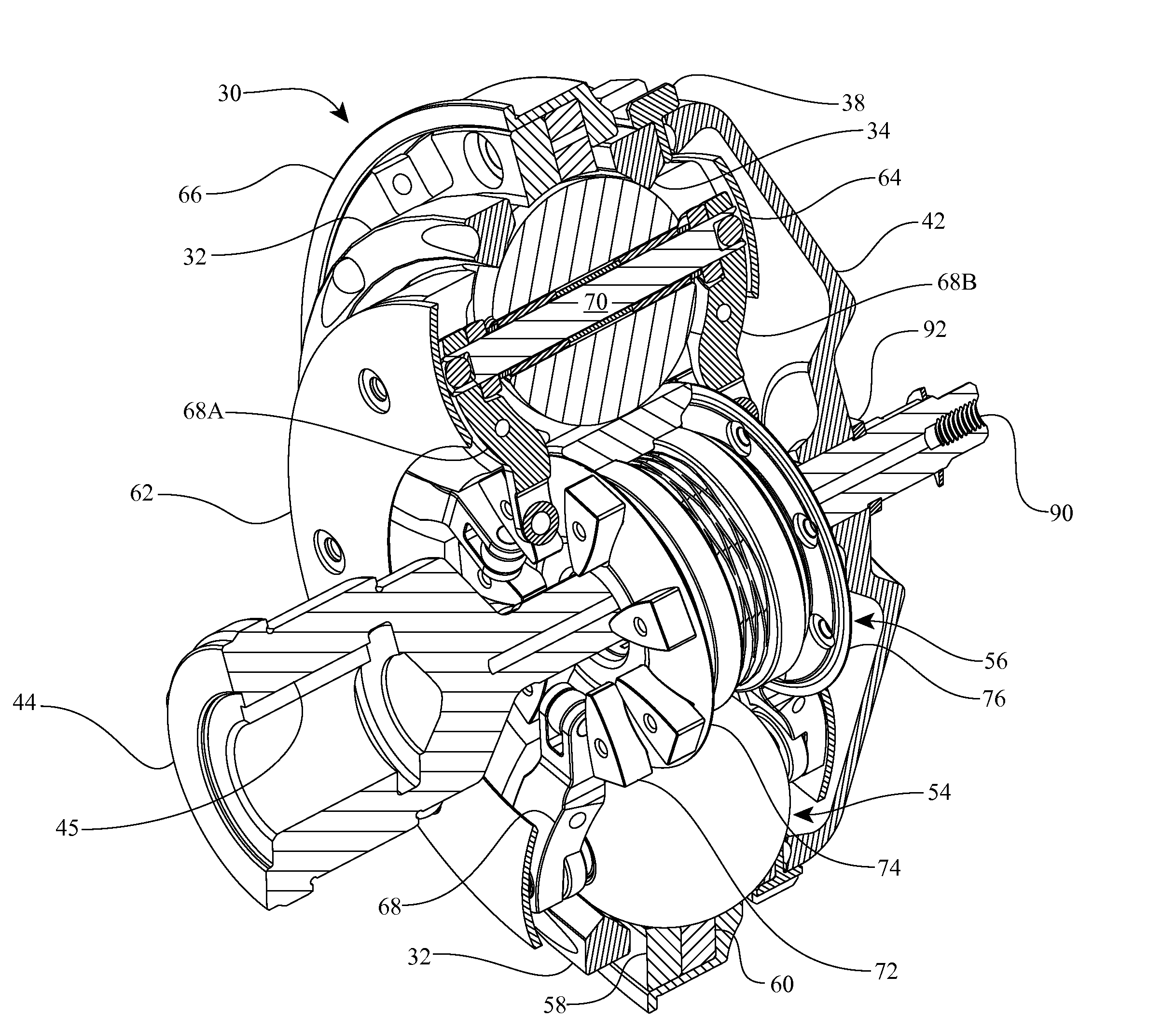
[0008]One aspect of the invention relates to a continuously variable accessory drive (CVAD) having an accessory device and a continuously variable transmission (CVT) coupled to the accessory device. The continuously variable transmission has a group of traction planets. Each traction planet can be adapted to rotate about a tiltable axis. The CVAD also includes a skew actuator operably coupled to the CVT. The skew actuator can be adapted to apply a skew condition to the CVT to tilt the axes of the traction planets.

[0009]Another aspect of the invention concerns a continuously variable accessory drive (CVAD) having a group of traction planets arranged angularly about a longitudinal axis of the CVAD. The CVAD can include a group of planet axles. Each planet axle is operably coupled to each traction planet. Each planet axle defines a tiltable axis of rotation f...


PUM

PropertyMeasurementUnit
Poweraaaaaaaaaa
Ratioaaaaaaaaaa

Abstract

Inventive embodiments are directed to components, subassemblies, systems, and/or methods for continuously variable accessory drives (CVAD). In one embodiment, a skew-based control system is adapted to facilitate a change in the ratio of a CVAD. In another embodiment, a skew-based control system includes a skew actuator coupled to a carrier member. In some embodiments, the skew actuator is configured to rotate a carrier member of a CVT. Various inventive traction planet assemblies can be used to facilitate shifting the ratio of a CVT. In some embodiments, the traction planet assemblies include legs configured to cooperate with the carrier members. In some embodiments, a traction planet assembly is operably coupled to the carrier members. Embodiments of a shift cam and a traction sun are adapted to cooperate with other components of the CVT to support operation and/or functionality of the CVT. Among other things, shift control interfaces for a CVT are disclosed.

Description

BACKGROUND OF THE INVENTION[0001]1. Field of the Invention[0002]The field of the invention relates generally to mechanical and / or electromechanical power modulation devices and methods, and more particularly to continuously and / or infinitely variable, planetary power modulating devices and methods for modulating power flow in a power train or drive, such as power flow from a prime mover to one or more auxiliary or driven devices.[0003]2. Description of the Related Art[0004]In certain systems, a single power source drives multiple devices. The power source typically has a narrow operating speed range at which the performance of the power source is optimum. It is preferred to operate the power source within its performance optimizing operating speed range. A driven device typically also has a narrow operating speed range at which the performance of the driven device is optimum. It is also preferred to operate the driven device within its performance optimizing operating speed range. A...

Claims


Application Information

Patent Timeline
IPC IPC(8): F16H37/02
CPCF02B67/04F16H15/42F16H61/664F16H63/067Y02T10/76Y10T29/49826F16H61/0021F16H15/503F16H61/0204Y10T477/619F16H15/50F16H2059/704F16H15/40F16H2061/6641F16H63/42F16H15/52Y02T10/60F16H59/40F16H61/6646F16H63/065
Inventor POHL, BRAD P.THOMASSY, FERNAND A.LOHR, CHARLES B.MCBROOM, SCOTT T.
Owner FALLBROOK INTPROP COMPANY
Why Eureka
Try Eureka