Storage device and data reading method thereof

a storage device and data technology, applied in the direction of digital signal error detection/correction, redundant data error correction, digital recording/reproduction, etc., can solve the problems of read error, processing is started, read error is likely to be caused in the magnetic disk

Inactive Publication Date: 2010-04-15
TOSHIBA STORAGE DEVICE CORP
View PDF9 Cites 6 Cited by
  • Summary
  • Abstract
  • Description
  • Claims
  • Application Information

AI Technical Summary

Problems solved by technology

A disk storage device in particular causes the read error due to cross-talk, vibration, and the external magnetic field, because a track pitch of the disk storage medium is narrow.
When the read error is detected, the read processing is started.
In such environments, a read error is likely to be caused in the magnetic disk by noise due to strong electromagnetic field or displacement of a head by external vibration.
Likewise, the read error of multi-value data is likely to be caused in the storage device such as a flash memory by noise due to the strong electromagnetic field.
Therefore, the external vibration or the noise occurred in some frequency causes the degree of the error to vary.
As a result, results of the majority decision may adversely be influenced and the capability of error correction may be deteriorated.

Method used


Image

  • Storage device and data reading method thereof
  • Storage device and data reading method thereof
  • Storage device and data reading method thereof

Examples


first embodiment

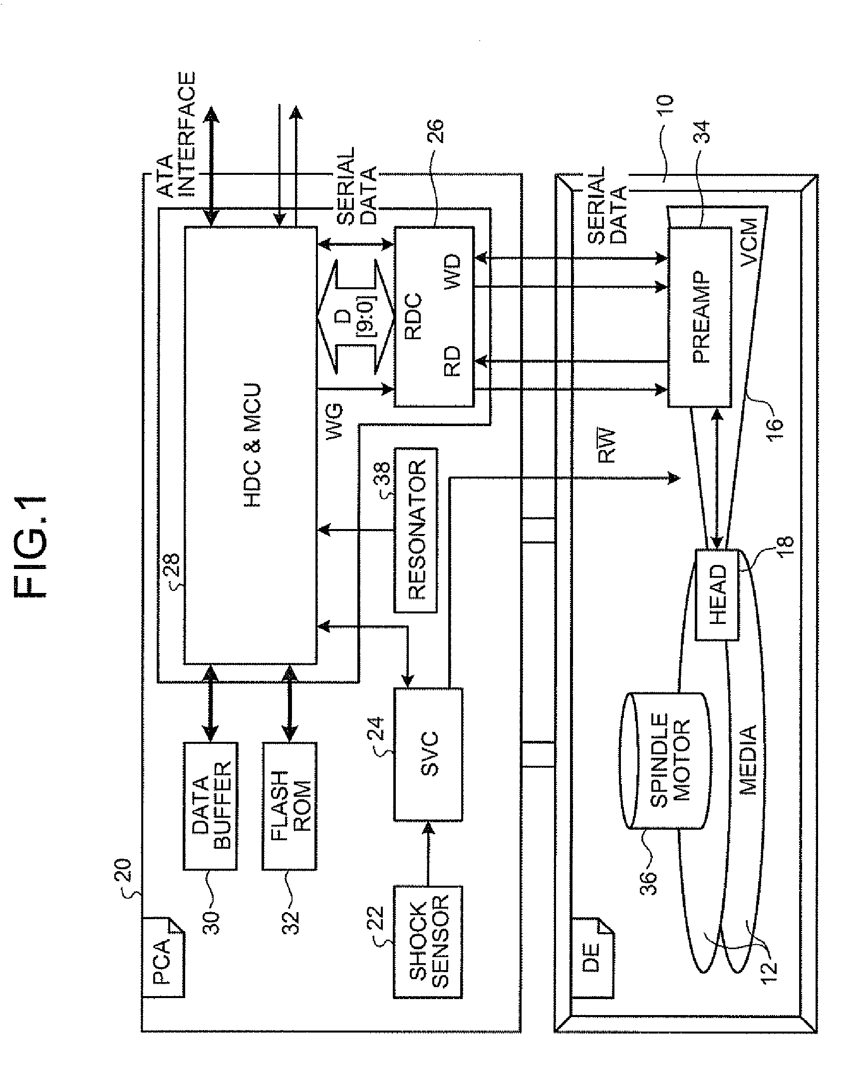
[0033]FIG. 1 is an exemplary block diagram of a storage device according to the Here, a magnetic disk device is explained as the storage device. As illustrated in FIG. 1, a magnetic disk 12 is provided with respect to a rotation shaft of a spindle motor 36. The spindle motor 36 rotates the magnetic disk 12. An actuator 16 includes a magnetic head 18 at a tip end thereof and moves the magnetic head 18 in the radial direction of the magnetic disk 12.

[0034]The actuator 16 includes a voice coil motor (VCM) having an arm rotating around the rotation shaft, a driving coil provided at the rear end of the arm, and a suspension (gimbal) provided at the tip end of the arm. The magnetic head 18 is provided at the suspension.

[0035]The actuator 16 is provided with a head IC (preamplifier) 34 including a write driver electrically connected to the magnetic head 18. The aforementioned configurations are held inside a disk enclosure 10.

[0036]The magnetic head 18 has a slider, a read element (MR ele...

second embodiment

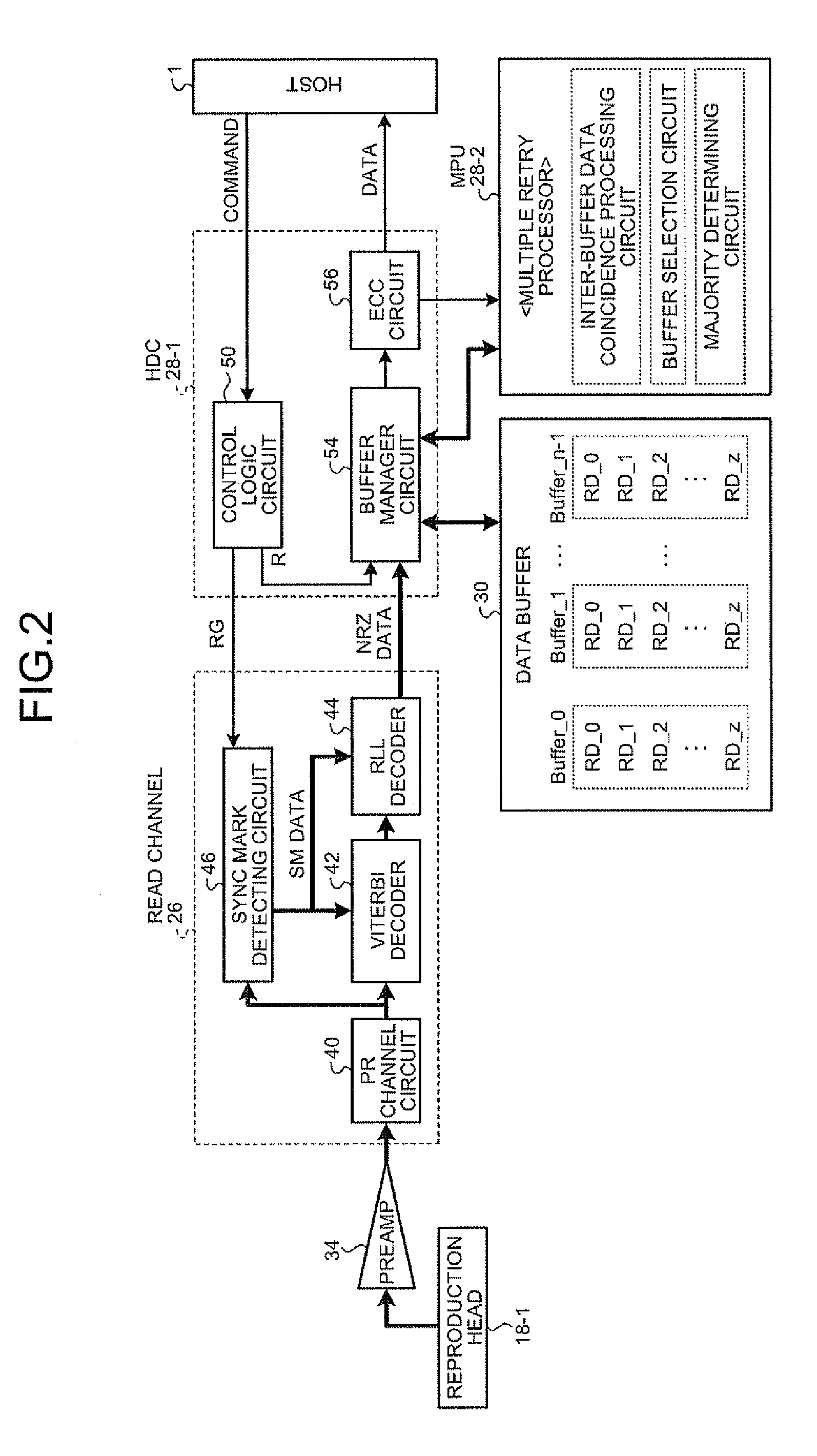
[0085]FIG. 14 is a block diagram of a read circuit and in particular, the block diagrams illustrates the read channel 26 and a HDC / MCU 28 as in FIG. 1.

[0086]In FIG. 14, the same parts as those in FIG. 2 are denoted by the same reference numerals. In other words, a read signal from the reproduction head (read element) 18-1 of the magnetic head 18 is input to the PR channel circuit 40 of the read channel 26 via the preamp 34. The PR channel circuit 40 includes a variable gain amplifier (VGA), an asymmetry correction circuit (ASC), a continuous Time filter (CTF), an analogue / digital converter (ADC), a finite impulse response filter (FIR), an AGC circuit, and the like.

[0087]The PR channel circuit 40 first adjusts the amplitude and asymmetry of the read signal, equalizes a waveform by the control filter, A-D converts the signal and waveform-shapes the PR (partial response) signal by the FIR.

[0088]The Sync mark detecting circuit 46 detects a Sync mark SM of a predetermined pattern from a...


PUM


Abstract

According to one embodiment, a data reading method of a storage device for reading data from a storage module, includes: reading data from the storage module; detecting an error in the data; reading, when the error is detected, the data several times; storing each data read several times in a buffer; calculating correlation between the data stored in the buffer; selecting data stored in the buffer with strong correlation so as to exclude data with low correlation from the selection; performing majority decision on the selected data or averaging the selected data; and outputting a result of the majority decision or the averaging as read data.

Description

CROSS-REFERENCE TO RELATED APPLICATIONS[0001]This application is based upon and claims the benefit of priority from Japanese Patent Application No. 2008-263881, filed Oct. 10, 2008, the entire contents of which are incorporated herein by reference.BACKGROUND[0002]1. Field[0003]One embodiment of the invention relates to a storage device and a data reading method of the storage device performing a retry sequence to reduce a read error.[0004]2. Description of the Related Art[0005]Various techniques have been employed to obtain accurate data from signals read out from recent storage devices, in accordance with an increase in a density of the storage devices. Such techniques that are used generally include error detection / correction processing and a retry sequence that retries data reading.[0006]A disk storage device in particular causes the read error due to cross-talk, vibration, and the external magnetic field, because a track pitch of the disk storage medium is narrow. Therefore, a t...

Claims


Application Information

Patent Timeline
Patent Type & Authority Applications(United States)
IPC IPC(8): G06F11/07
CPCG11B2020/183G11B20/18
Inventor KANAYA, HIROSHI
Owner TOSHIBA STORAGE DEVICE CORP
Why Eureka
Try Eureka