Display system, network interactive display device, terminal, and control program

Active Publication Date: 2010-04-15
SEIKO EPSON CORP
View PDF32 Cites 38 Cited by
  • Summary
  • Abstract
  • Description
  • Claims
  • Application Information

AI Technical Summary

Benefits of technology

[0104]In the network interactive display device of a preferred embodiment of the present invention, the image synthesizer may synthesize the captured imag

Problems solved by technology

However, no such a display system satisfying the need exist.
For one reason, a large throughput is required of a

Method used


Image

  • Display system, network interactive display device, terminal, and control program
  • Display system, network interactive display device, terminal, and control program
  • Display system, network interactive display device, terminal, and control program

Examples


first embodiment

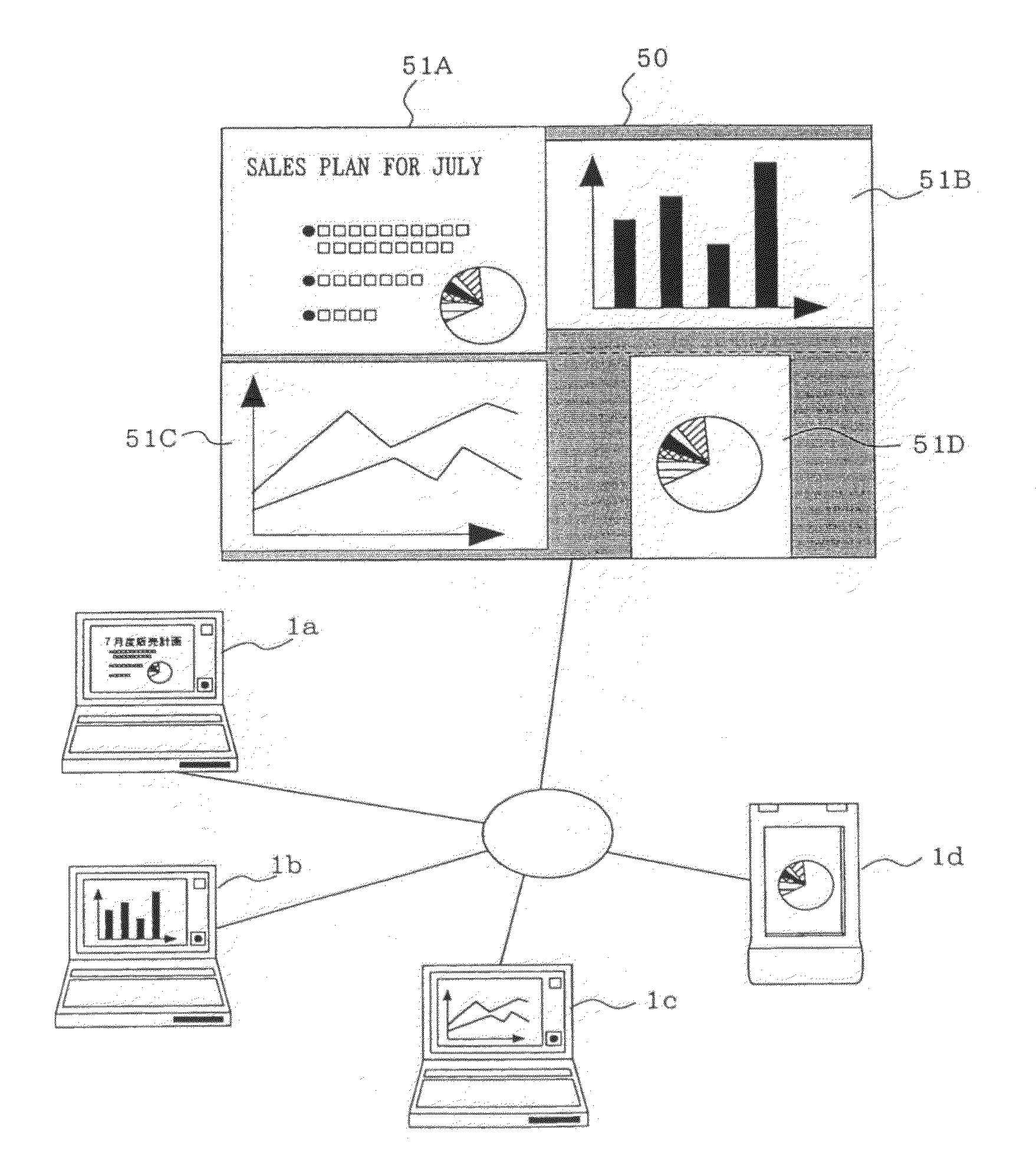
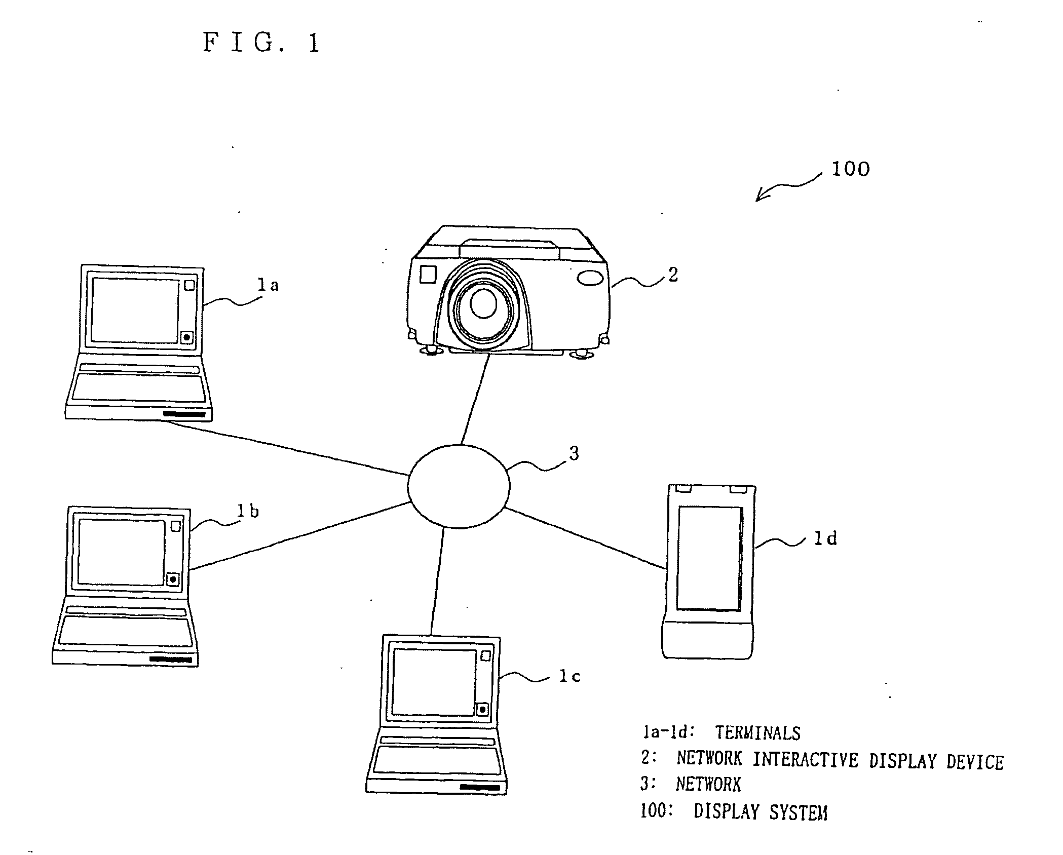
[0152]FIG. 1 illustrates a network of a display system 100 including a network interactive display device 2 in accordance with preferred embodiments of the present invention.

[0153]The display system 100 includes a plurality of terminals (only four terminals 1a, 1b, 1c, and 1d are shown in FIG. 1), and the network interactive display device 2 (a projector here) having a multi-window screen presentation function as one of major functions of the present invention. The plurality of terminals 1 are respectively connected to the network interactive display device 2 (hereinafter simply referred to the display device 2) through a network 3 in a two-way communication based on the TCP / IP protocol. A unique name is provided beforehand to each terminal 1 (hereinafter referred to as a terminal name). The network 3 may be any of a LAN (Local Area Network), a radio LAN, and a near-field communication radio LAN such as Bluetooth (Tradename of Bluetooth SIG Inc., U.S.A.).

[0154]The display system 100...

second embodiment

[0260]FIG. 1 illustrates a network of a display system 100 including a network interactive display device 2 in accordance with preferred embodiments of the present invention.

[0261]The display system 100 includes a plurality of terminals (only four terminals 1a, 1b, 1c, and 1d are shown in FIG. 1), and the network interactive display device 2 (a projector here) having a multi-window screen presentation function as one of major functions of the present invention. The plurality of terminals 1 are respectively connected to the network interactive display device 2 through a network 3 in a two-way communication based on the TCP / IP protocol. A unique name is provided beforehand to each terminal 1 (hereinafter referred to as a terminal name). The network 3 may be any of a LAN (Local Area Network), a radio LAN, and a near-field communication radio LAN such as Bluetooth (Tradename of Bluetooth SIG Inc., U.S.A.).

[0262]The display system 100 allows screens presented on the plurality of terminal...


PUM


Abstract

A technique for presenting display screens of a plurality terminals connected to a network on a multi-window screen of a display screen of a display device. A communication unit receives image data captured and then sent by each terminal having a screen capture function. A display control unit controls an image synthesizer to synthesize the captured image data into single screen multi-window format data. A multi-window screen is thus presented.

Description

[0001]This is a Continuation of application Ser. No. 10 / 623,518 filed Jul. 22, 2003. The disclosure of the prior application is hereby incorporated by reference herein in its entirety.BACKGROUND OF THE INVENTION[0002]1. Field of the Invention[0003]The present invention relates to a technique that presents screens of a plurality terminals connected to a network on a single screen of a display device in a multi-window presentation fashion.[0004]2. Description of the Related Art[0005]FIG. 25 shows a structure of a conventional display system. Connected to a network 210 as shown are a projector 220, a notebook computer 230, and desk-top computers 251, 252, 253, and 254 as network interactive display devices. Further connected to the network 210 are tablets 261, 262, 263, and 264, each of which directly inputs drawings to the projector 220 and inserts data in the already projected drawings. A screen capture software program is already installed on each of the notebook computer 230 and th...

Claims


Application Information

Patent Timeline
IPC IPC(8): G06F3/048G09F9/00G09G3/36G09G5/00H04N5/74H04N7/14
CPCG06F3/1454G06Q10/10H04N7/15H04N21/4312G06F3/0484H04N21/4402H04N21/64792G06F3/0481H04N21/4314
Inventor NAGANO, MIKIYOSHIKUNI, NORIHIRO
Owner SEIKO EPSON CORP
Why Eureka
Try Eureka