Coal ash treatment method and apparatus

a treatment method and coal ash technology, applied in the field of coal ash treatment methods and equipment, can solve the problems of increasing the mercury concentration in the cement kiln, air pollution, and difficulty in removing the mercury contained in the exhaust gas of the cement kiln, and achieve the effect of decreasing the mercury concentration and increasing the mercury concentration

Inactive Publication Date: 2010-04-22
TAIHEIYO CEMENT CORP
View PDF7 Cites 1 Cited by
  • Summary
  • Abstract
  • Description
  • Claims
  • Application Information

AI Technical Summary

Benefits of technology

[0020]Then, with this coal ash treatment apparatus, as described above, the ash separated by the first separating means may be utilized in the cement manufacturing facility as a cement raw material, and from the unburned carbon separated by the first separating means can be separate mercury by the second separating means, which makes it possible to utilize unburned carbon from which mercury is removed as a fuel in the cement manufacturing facility without increasing mercury concentration in the cement kiln exhaust gas.
[0021]As described above, with the coal ash treatment method and apparatus according to the present invention, coal ash may effectively be utilized while decreasing mercury concentration in cement kiln exhaust gas.

Problems solved by technology

However, it is very difficult to remove mercury contained in cement kiln exhaust gas at low concentration from a large quantity of exhaust gas, and increase in mercury concentration in the cement kiln exhaust gas may be a cause of air pollution as well as a primary factor impeding enlarged utilization of recycle resources such as fly ash.

Method used


Image

  • Coal ash treatment method and apparatus
  • Coal ash treatment method and apparatus

Examples


Embodiment Construction

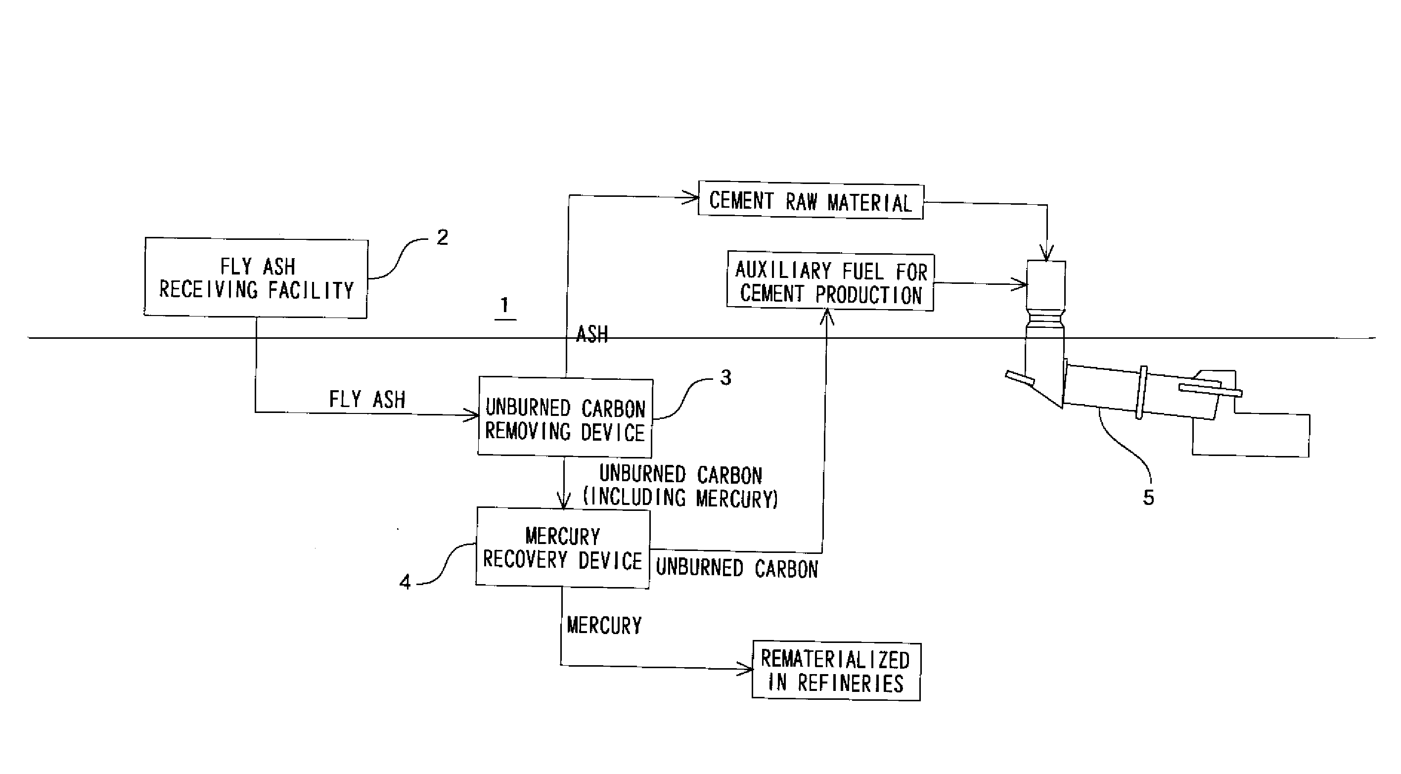
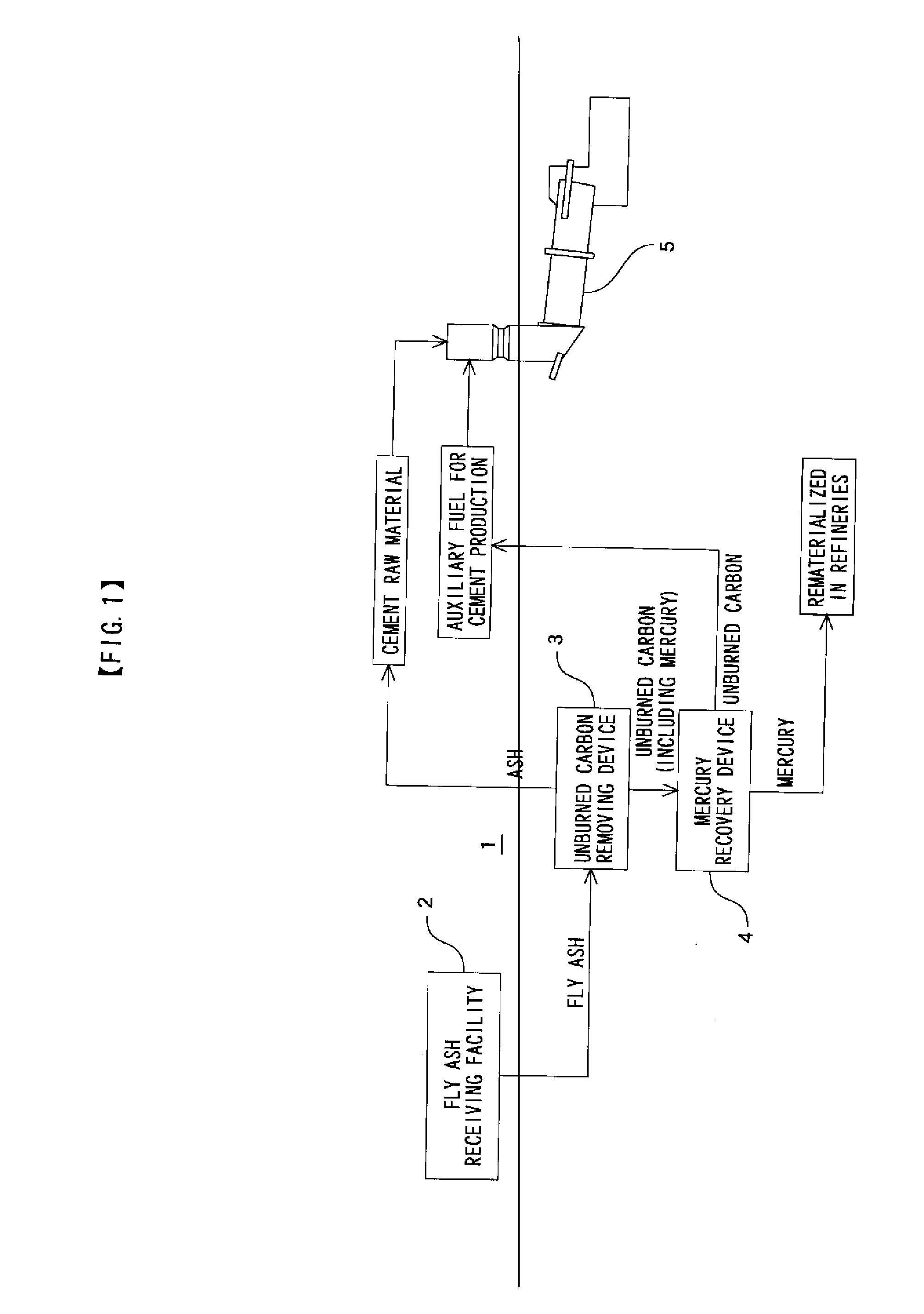
[0023]Next, an embodiment of the present invention will be explained with reference to a drawing. In the below explanation, fly ash generated in coal firing power plants, etc. is exemplarily introduced as a coal ash that is a target treated by coal ash treatment method and apparatus according to the present invention.

[0024]As illustrated in FIG. 1, a coal ash treatment apparatus 1 of the present invention comprises a fly ash receiving facility 2, an unburned carbon removing device 3 and a mercury recovery device 4.

[0025]The fly ash receiving facility 2 is for receiving fly ash generated in coal firing power plants, etc. to effectively utilize it in a cement manufacturing facility, and is provided with a pneumatic-pumping-type tank and others.

[0026]The unburned carbon removing device 3 is installed to remove unburned carbon from fly ash fed from the fly ash receiving facility 2 by an electrostatic method, a flotation method or the like to obtain ash and unburned carbon.

[0027]The merc...


PUM

PropertyMeasurementUnit
concentrationaaaaaaaaaa
heating vaporization atomic absorption methodaaaaaaaaaa

Abstract

To effectively utilize coal ash while reducing mercury concentration in cement kiln exhaust gas. Coal ash is received from a thermal power plant or the like; the received coal ash is separated into ash and unburned carbon; the separated ash is utilized in a cement manufacturing facility as a cement raw material; and the separated unburned carbon is utilized in the cement manufacturing facility in accordance with mercury concentration in gas exhausted from a cement kiln of the cement manufacturing facility. In case that the mercury concentration in the gas exhausted from the cement kiln of the cement manufacturing facility is high, in the coal ash, unburned carbon with high mercury content can be treated in facilities other than the cement manufacturing facility without feeding the unburned carbon to the cement manufacturing facility, or the quantity of such unburned carbon fed to the cement manufacturing facility can be adjusted. It is possible to separate mercury from the separated unburned carbon, and utilize the unburned carbon from which mercury is separated in the cement manufacturing facility as a fuel.

Description

CROSS-REFERENCE TO RELATED APPLICATIONS[0001]The present application claims priority to International Application No. PCT / JP2007 / 073146 filed on Nov. 30, 2007, which claims priority to Japanese Patent Application No. 2006-327870 filed on Dec. 5, 2006.STATEMENT RE: FEDERALLY SPONSORED RESEARCH / DEVELOPMENT[0002]Not ApplicableBACKGROUND OF THE INVENTION[0003]1. Technical Field of the Invention[0004]The present invention relates to a coal ash treatment method and apparatus, and more particularly to the apparatus and the method for effectively utilizing fly ash and the like generated in coal firing power plants, etc. as a cement raw material while reducing mercury concentration in cement kiln exhaust gas.[0005]2. Description of the Related Art[0006]Fly ash generated in coal firing power plants or the like has been used for cement admixture, concrete admixture, raw materials for artificial lightweight aggregates, etc. In these cases, since fly ash containing much unburned carbon causes va...

Claims


Application Information

Patent Timeline
Patent Type & Authority Applications(United States)
IPC IPC(8): C04B7/38C04B7/44B07C99/00
CPCB03B9/04C04B7/28F27B7/20C04B7/38C04B7/4423C04B7/364Y02P40/125Y02P40/10B09B5/00C04B7/44
Inventor NAKAMURA, TOMOMICHIKONDO, HISASHISAITO, SHINICHIRO
Owner TAIHEIYO CEMENT CORP
Why Eureka
Try Eureka