
Make-up brushes, their components and methods of using them

a technology of brushes and brushes, applied in the field of makeup brushes, can solve the problems of inconvenient removal of brushes, inability to remove brushes of this type, and inability to remove prior art paint brushes or unidentified brushes, etc., and achieve the effects of quick and simple removal, quick and easy replacement, and quick and simple removal

Inactive Publication Date: 2010-04-22
SHRIER LINDA FAYE
View PDF36 Cites 59 Cited by
  • Summary
  • Abstract
  • Description
  • Claims
  • Application Information

AI Technical Summary

Benefits of technology

[0011]It is a still further object of the invention to provide a novel method and brush for avoiding the transfer of harmful materials such as pathological bacteria and the like from one person to another.
[0012]It is a still further object of the invention to provide a convenient and inexpensive method of avoiding the use of contaminated products when applying cosmetics.
[0013]It is a still further object of the invention to provide a method of applying cosmetics which avoids carry over from a contaminated brush head to the person using the cosmetic applicator.
[0014]In accordance with the above and further objects of the invention, an ornamental design is provided for a make-up brush with a replaceable brush head. The make-up brush is symmetrical, attractive, sanitary and easy to use. The replaceable brush head can be quickly and easily connected to the handle or disconnected from the handle. It is connected to the handle by pushing it into a snap-on fastener in the handle and is released from the handle by depressing a push button at the end of the handle. Depressing the push button opens the snap-on fastener.
[0019]As can be understood from the above description, the make-up brush and method of applying makeup of this invention has several advantages, such as for example: (1) the brush head can be quickly and simply removed by pushing a button at the end of the handle to permit the brush head to drop off for disposal; (2) the brush head can be removed without it moving close to the arm or around the body but can be removed at a distance by pressing the button at the end of the handle with the same hand that is holding the make-up brush; and (3) the brush head can be removed quickly and easily without manipulating that might cause powder or liquid to fall onto the person and be as quickly and easily replaced with a new sterile brush head.

Problems solved by technology

The prior art disposable-head cosmetic brushes have several disadvantages, such as: (1) the handle and brush head can only be separated by holding the brush head with one hand and handle with the other in such a position that the bristles of the brush head may cause powder or the like to drop onto or be otherwise deposited onto the user during the removal process; and (2) the action of threading or unthreading the brush head from the handle is relatively slow and tedious and done in a position which could cause cosmetic powders on the head to be inadvertently spread to other surfaces.
The prior art paint brushes or unidentified brushes of this type have a disadvantage of requiring substantial manipulation to enable the radially extending member to be properly insertable into the external member.
At best, this connection is not firm because of the difficulty of exerting substantial force radially outwardly into a tightly gripped opening so that for easy insertion, the connections are typically wobbly.
This type of prior art non-cosmetic utilitarian brush has several disadvantages such as for example: (1) they are not symmetrical but have a handle bent to enable access to difficult places to clean; (2) substantial force is needed to remove the head because of the large frictional area of the sleeve holding the head to the handle and the location of this force at a substantial distance from the center of the structure; and (3) under some circumstances, such as very small brushes, it is unsightly and not easy to use.
The first and second flat members are separated by a long stem and a fastener on both sides of the second flat member to hold the stem in place and the two flat members do not form a secure wobble free socket suitable for a brush head.
This type of snap fastener has not been taught for use in brush holders and has the disadvantage of not providing a support surface to hold the brush from wobbling.

Method used


Image

  • Make-up brushes, their components and methods of using them
  • Make-up brushes, their components and methods of using them
  • Make-up brushes, their components and methods of using them

Examples


Embodiment Construction

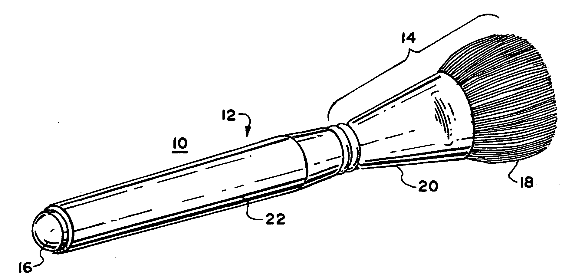
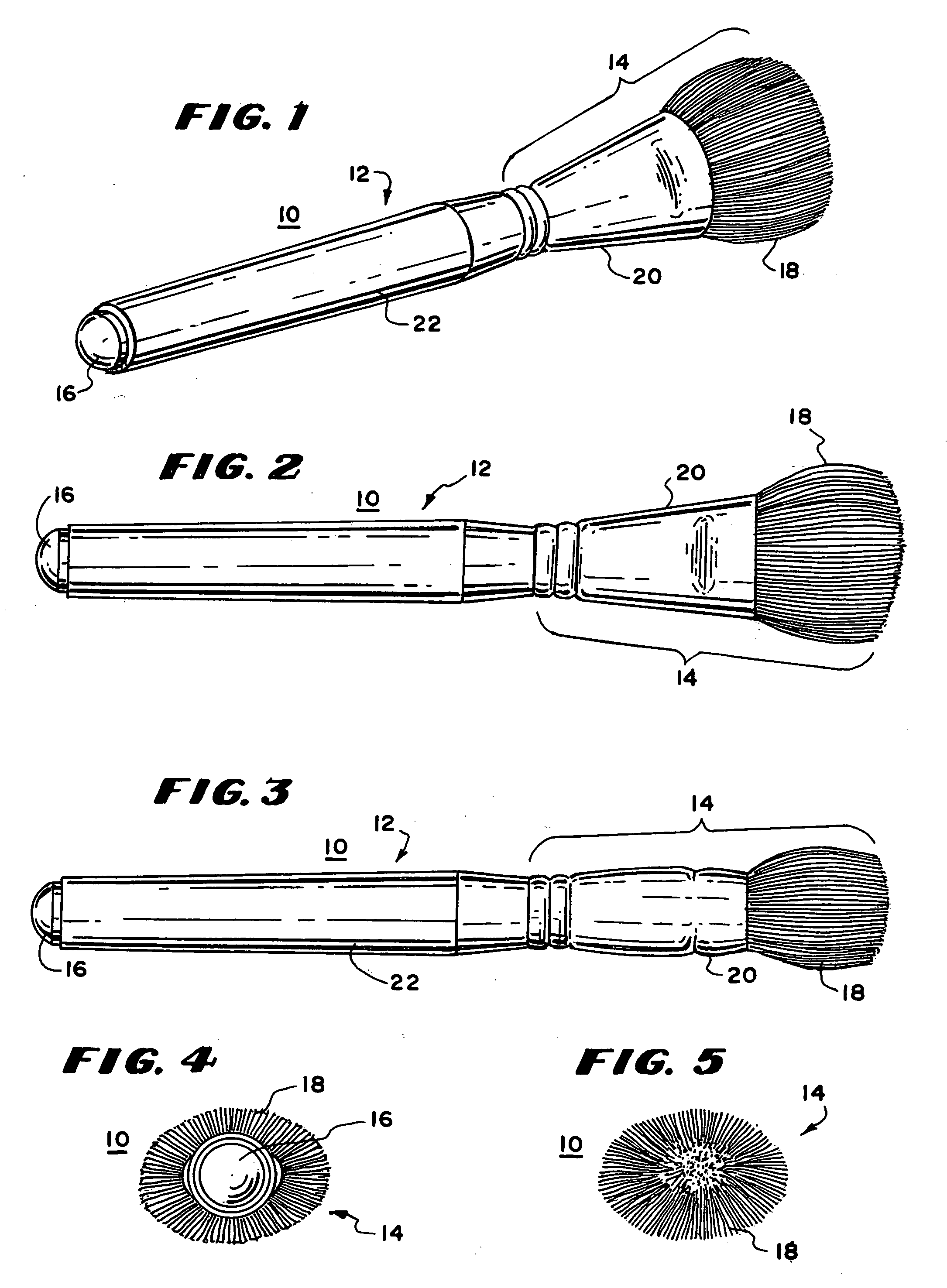
[0057]In FIGS. 1-5, there are shown a perspective view, an elevational view, a top view, a left side view and a right side view respectively of a make-up brush 10 having a brush head 14, a stem or handle portion 12 and an actuator button 16. The brush head 14 includes a plurality of bristles shown at 18 held by a ferrule 20. The stem or handle portion 12 includes an outer wall or casing 22 extending from the ferrule 20 to the actuator button 16. In FIGS. 4 and 5, there are shown a plan and bottom of the make-up brush 10. The makeup brush in the embodiment of FIGS. 1-5 provides bristles formed into a narrow somewhat rectangular pattern for application in a narrow line or a wider area. It has the decorative appearance provided by an actuator button 16 on one end, a symmetrical stem 12, a ferrule 20 and bristles 18 on the other end.

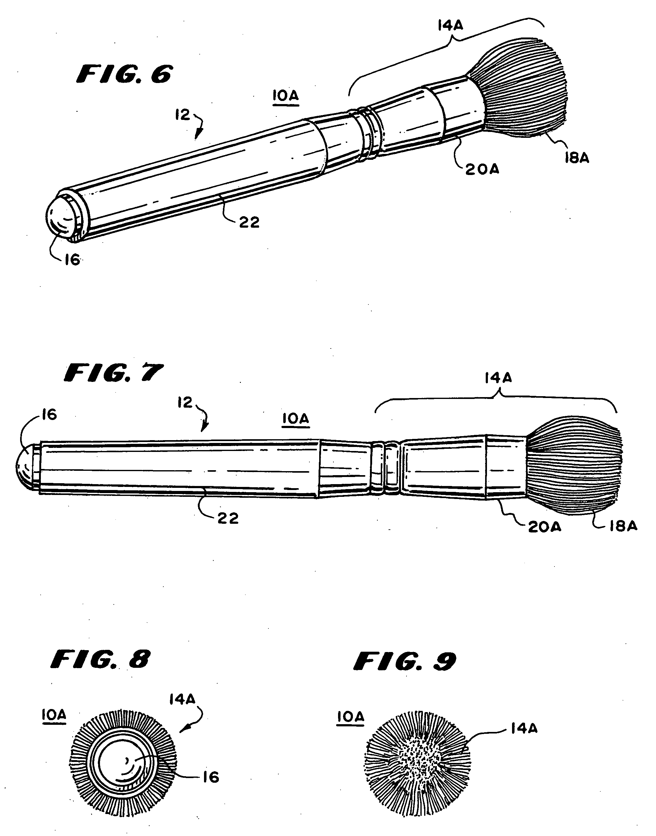
[0058]In FIGS. 6-9, there are shown a perspective view, an elevational view, a left side bottom view and a right side view respectively of another embodimen...


PUM


Abstract

An ornamental design of a make-up brush with a replaceable brush head includes a handle portion having an elongated central axis and a snap fastener. A first portion of the snap fastener is fastened to the handle portion and a second portion of the snap fastener is fastened to a replaceable head. A third portion of the snap fastener includes a push button aligned with the snap fastener along an elongated central axis, wherein the decorative make-up brush is symmetrical. The replaceable head and handle portion are wobble free secured.

Description

BACKGROUND OF THE INVENTION[0001]This invention relates to make-up brushes, and more particularly to disposable make-up brushes, their components, methods of making them and methods of using them.[0002]It is known to provide for replacement of brush heads in make-up brushes. The prior art cosmetic brushes with replaceable heads include a screw attachment fixture to connect the stem to the head. One of the brush head and stem or an attachment to the brush head and stem includes an extending bolt with external threads and the other a hole with internal threads so the two may be threaded together. An example of the prior art cosmetic brushes with a replaceable head is disclosed in U.S. Pat. No. 5,926,903.[0003]The prior art disposable-head cosmetic brushes have several disadvantages, such as: (1) the handle and brush head can only be separated by holding the brush head with one hand and handle with the other in such a position that the bristles of the brush head may cause powder or the...

Claims


Application Information

Patent Timeline
Patent Type & Authority Applications(United States)
IPC IPC(8): A46B5/00A46B5/02A46B9/02A46B7/04
CPCA46B7/04A46B2200/1046A46B7/042
Inventor SHRIER, LINDA FAYEWOOD, DAVID SCOTT
Owner SHRIER LINDA FAYE
Learn More