Optical identification tag, reader and system

a technology of optical identification and reader, applied in the field of optical identification tags, a reader and a system, can solve the problems of limiting applications and the inability of rfid tags to apply to applications which require a very small-sized identification tag, and achieve the effect of simplifying the circuit configuration and significantly reducing the area of identification tags

Inactive Publication Date: 2010-04-22
SEOUL NAT UNIV R&DB FOUND
View PDF6 Cites 87 Cited by
  • Summary
  • Abstract
  • Description
  • Claims
  • Application Information

AI Technical Summary

Benefits of technology

[0010]According to the present invention, an existing RFID may be advantageously replaced by an optical identification tag, and an optical identification reader and system used for the optical identification tag of the present invention.
[0011]In addition, the optical identification tag, and the optical identification reader and system used for the optical identification tag according to the present invention employ a solar cell and a light emitter instead of antennas which occupy the largest area in the existing RFID tag, so that an area of the identification tag can be significantly reduced.
[0012]In addition, the optical identification tag, and the optical identification reader and system used for the optical identification tag according to the present invention convert a baseband signal into an optical signal to transmit and / or receive the signal, so that an RF circuit is not required, which thus leads to a simplified configuration of a circuit used for transceiving the signal.
[0013]In addition, the optical identification tag, and the optical identification reader and system used for the optical identification tag according to the present invention may be advantageously applied to applications requiring a very small identification tag (e.g., jewelry and so forth).

Problems solved by technology

However, Such an RFID tag has a relatively large area, which thus has a limit to applications.
As such, the RFID tag is big, so that the RFID tag cannot be applied to applications which require a very small-sized identification tag.

Method used


Image

  • Optical identification tag, reader and system
  • Optical identification tag, reader and system
  • Optical identification tag, reader and system

Examples


Embodiment Construction

[0025]The present invention will now be described more fully hereinafter with reference to the accompanying drawings, in which exemplary embodiments of the invention are shown. This invention may, however, be embodied in different forms and should not be construed as limited to the embodiments set forth herein. Rather, these embodiments are provided so that this disclosure will be thorough and complete, and will fully convey the scope of the invention to those skilled in the art. In the drawings, the thickness of layers and regions are exaggerated for clarity. Like numbers refer to like elements throughout the specification.

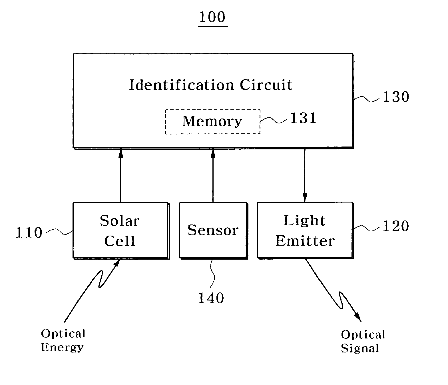
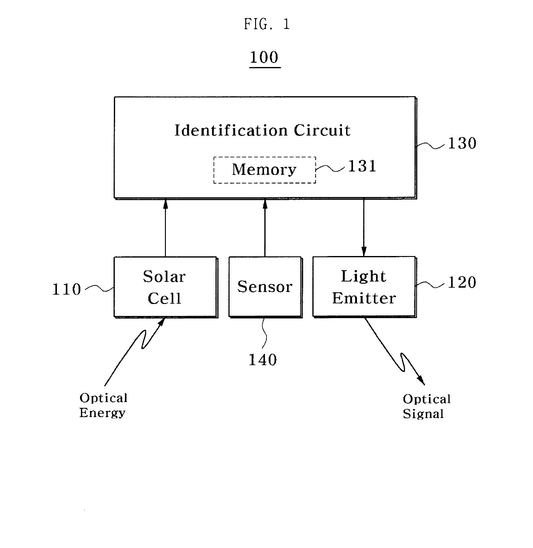
[0026]FIG. 1 illustrates an optical identification tag according to a first exemplary embodiment of the present invention. Referring to FIG. 1, an optical identification tag 100 includes a solar cell 110, a light emitter 120, and an identification circuit 130. The optical identification tag 100 may further include a sensor 140.

[0027]The solar cell 110 converts in...


PUM


Abstract

The present invention relates to an optical identification tag, a reader, and a system, and more particularly, to an optical identification tag which transmits its identification information using energy input in an optical form, and an optical identification system and reader using the optical identification tag. The present invention provides an optical identification tag and an optical identification reader. The optical identification tag includes a solar cell for converting incident light into an electrical energy, a circuit for providing a transmitted electrical signal corresponding to identification information, and a light emitter for providing a transmitted optical signal corresponding to the transmitted electrical signal, and the optical identification reader provides the incident light to the optical identification tag, and receives the transmitted optical signal from the optical identification tag.

Description

TECHNICAL FIELD [0001]The present invention relates to an optical identification tag, a reader and a system, and more particularly, to an optical identification tag which transmits its identification information using energy input in an optical form, and an optical identification system and reader using the optical identification tag.BACKGROUND ART [0002]An identification system according to the related art includes a radio frequency identification (RFID) system. The RFID system is a data recognition system which may read out identification information stored in an RFID tag by a request of an RFID reader, and uses an RF signal for transmitting the identification information. The RFID tags are mainly divided into an active RFID tag using a battery and a passive RFID tag not using a battery. The passive RFID tag does not require the battery and costs less, so that it can be used permanently and is widely employed.[0003]The RFID tag has an identification circuit and an antenna. The ide...

Claims


Application Information

Patent Timeline
Patent Type & Authority Applications(United States)
IPC IPC(8): G06F17/00G06K7/10G06K19/07H04B10/00
CPCG06K19/0728G06K19/0723G06K19/07G06K17/00H04B5/02
Inventor KWON, SUNGHOONPARK, YOUNGJUNEKIM, SUHWAN
Owner SEOUL NAT UNIV R&DB FOUND
Why Eureka
Try Eureka