
Light sensing circuit, touch panel including the same, and method of driving the light sensing circuit

Active Publication Date: 2010-04-22
SAMSUNG DISPLAY CO LTD
View PDF10 Cites 59 Cited by
  • Summary
  • Abstract
  • Description
  • Claims
  • Application Information

AI Technical Summary

Benefits of technology

[0012]Aspects of the invention relate to a light sensing circuit that can accurately detect the brightness of light incident on a photodiode by removing a current component generated due to ambient temperature from current generated by the photodiode, a touch panel including the light sensing circuit, and a method of driving the light sensing circuit.

Problems solved by technology

However, users who are not skilled in using such a mouse, keyboard, or remote control have difficulty using these input devices.
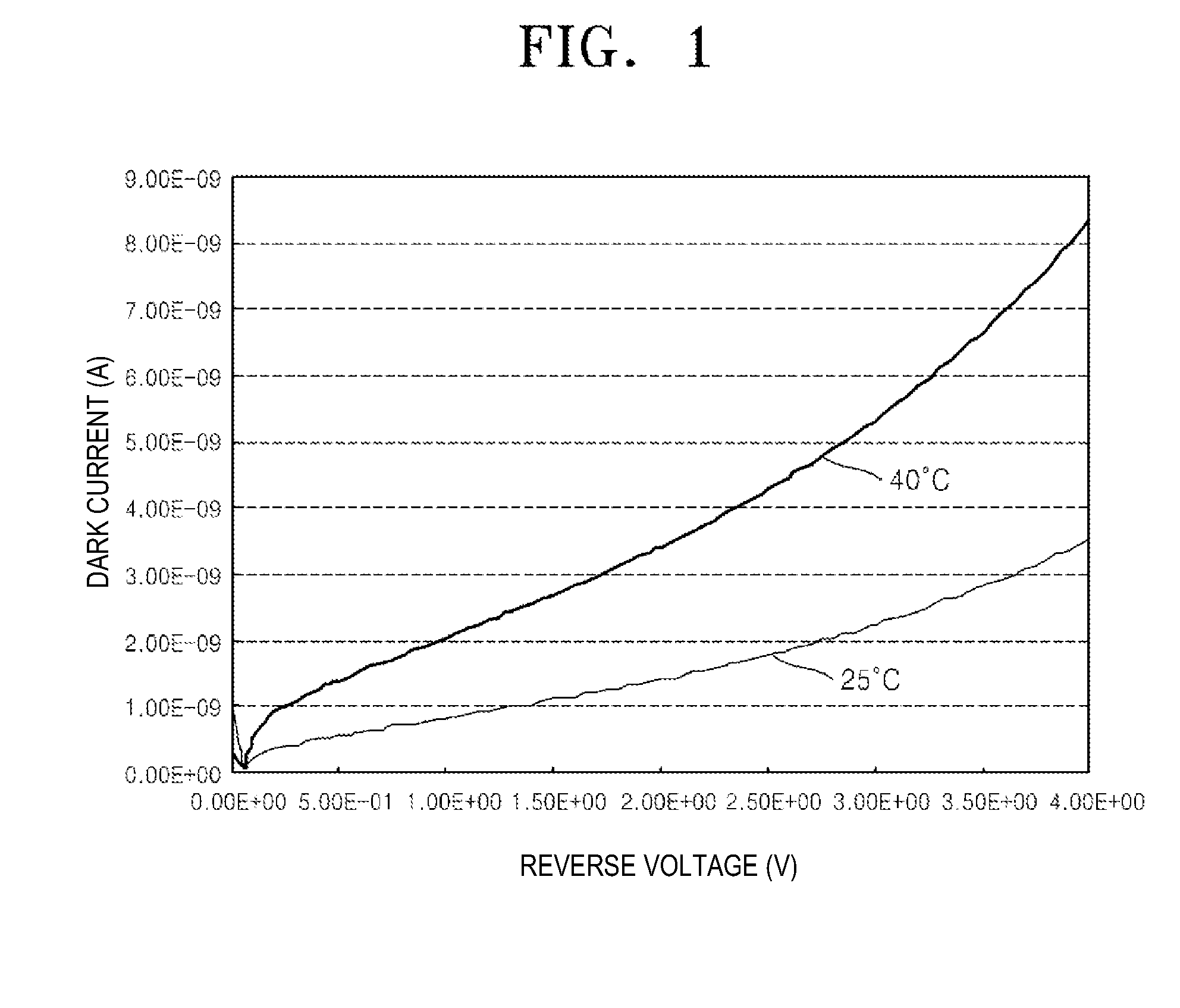
However, the current generated by the photodiode is affected by the temperature of the photodiode or the temperature of ambient air surrounding the photodiode as well as by the brightness of the light incident on the photodiode.
Hence, although light with the same brightness is incident on the photodiode, the detected brightness as indicated by the current flowing in the photodiode varies depending on the ambient temperature, which can cause errors in determining whether a user has touched the touch panel.

Method used


Image

  • Light sensing circuit, touch panel including the same, and method of driving the light sensing circuit
  • Light sensing circuit, touch panel including the same, and method of driving the light sensing circuit
  • Light sensing circuit, touch panel including the same, and method of driving the light sensing circuit

Examples


Embodiment Construction

[0044]Reference will now be made in detail to embodiments of the invention, examples of which are shown in the accompanying drawings, wherein like reference numerals refer to like elements throughout. The embodiments are described below in order to explain the invention by referring to the figures.

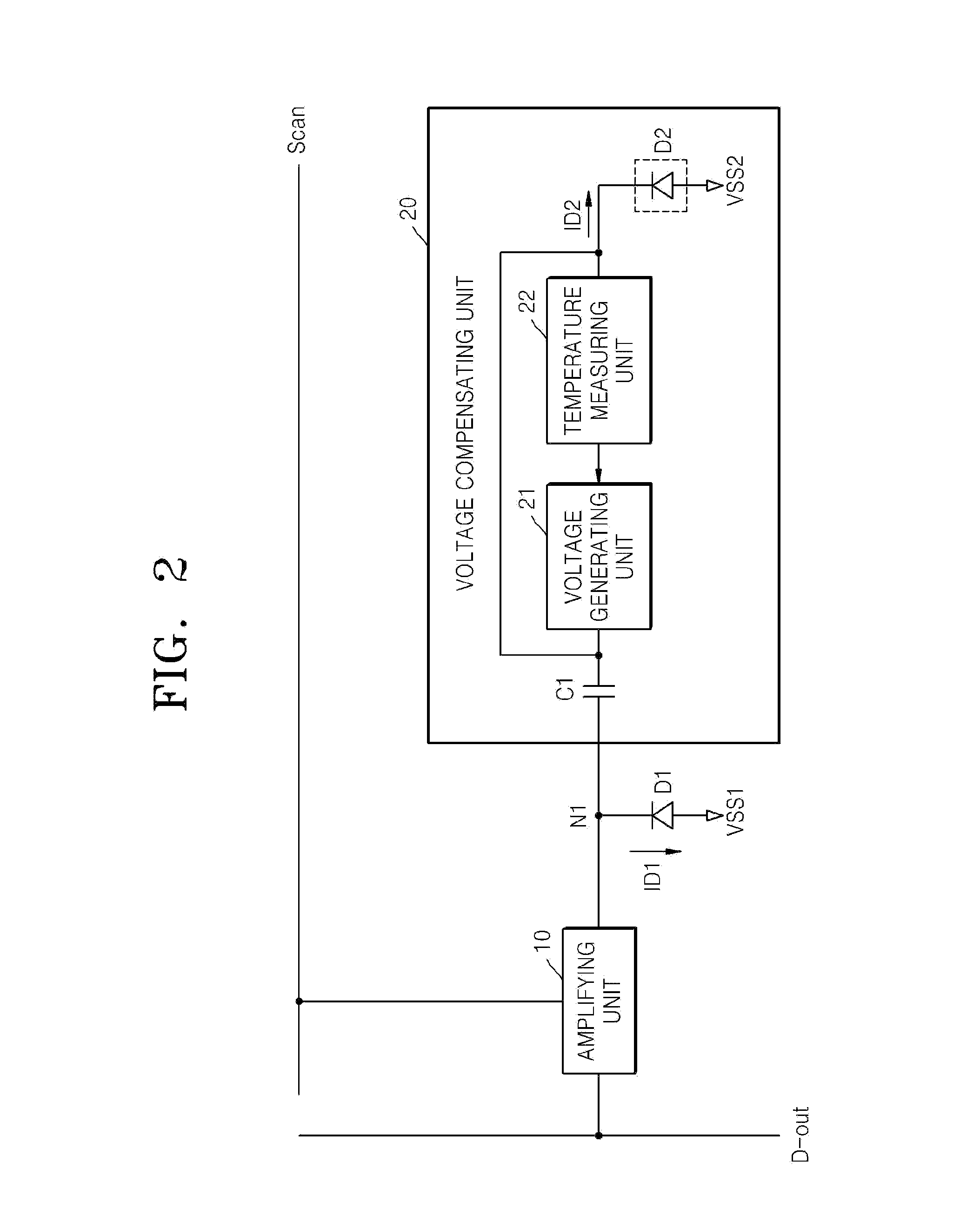
[0045]FIG. 2 shows a light sensing circuit according to an aspect of the invention. Referring to FIG. 2, the light sensing circuit includes a photodiode D1, an amplifying unit 10, and a voltage compensating unit 20. The photodiode D1 receives external light and generates a first current ID1. The photodiode D1 includes an anode and a cathode. A first ground voltage VSS1 is applied to the anode of the photodiode D1. The cathode of the photodiode D1 is connected to a first node N1. The photodiode D1 is reverse biased, unlike a typical diode. Accordingly, the potential of the anode must be lower than the potential of the cathode. If light is incident from the outside while the photodiode D1 is...


PUM


Abstract

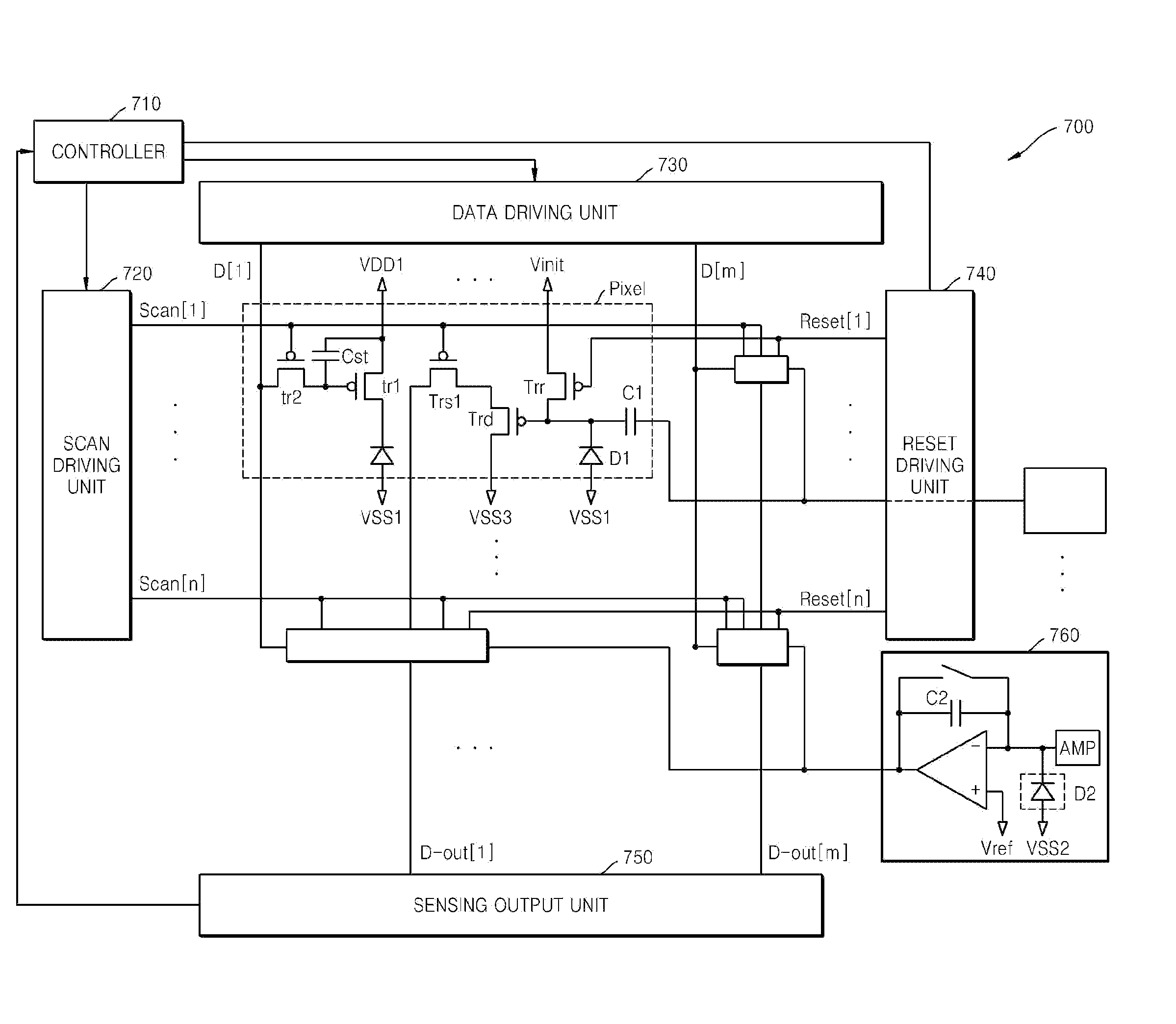
A light sensing circuit of a touch panel includes a photodiode including an anode and a cathode; a driving transistor including a gate electrode connected to the cathode of the photodiode, a first electrode to receive a first ground voltage, and a second electrode; a first switching transistor including a first electrode connected to the second electrode of the driving transistor, a second electrode to output a data signal, and a gate electrode to receive a scan signal; a first capacitor including a first terminal connected to the cathode of the photodiode, and a second terminal; and a voltage compensating unit to apply a compensation voltage to the second terminal of the first capacitor.

Description

CROSS-REFERENCE TO RELATED APPLICATIONS[0001]This application claims the benefit of Korean Patent Application No. 10-2008-0102112 filed on Oct. 17, 2008, in the Korean Intellectual Property Office, the disclosure of which is incorporated herein by reference in its entirety.BACKGROUND OF THE INVENTION[0002]1. Field of the Invention[0003]Aspects of the invention relate to a light sensing circuit, a touch panel including the same, and a method of driving the light sensing circuit, and more particularly, to a light sensing circuit that can accurately detect the brightness of light incident on a photodiode, a touch panel including the light sensing circuit, and a method of driving the light sensing circuit.[0004]2. Description of the Related Art[0005]In general, input devices, such as a mouse or a keyboard, are used to input a command to a computer. A remote control, which is also an input device, is used to control a device, such as a digital television, so that a user can select a spec...

Claims


Application Information

Patent Timeline
IPC IPC(8): G06F3/042H01J43/30
CPCG06F3/042G06F3/0412G06F3/0304G06F3/0354
Inventor AHN, SOON-SUNGPARK, YONG-SUNGKIM, DO-YOUBCHOI, DEOK-YOUNGCHOI, IN-HO
Owner SAMSUNG DISPLAY CO LTD
Learn More