Imaging apparatus, imaging method and program

a technology of imaging apparatus and output video, applied in the direction of television system, exposure control, instruments, etc., can solve the problems of unnatural output video, unnatural output video output, unnatural user perception of output video from imaging apparatus, etc., and achieve the effect of stable composite imag

Active Publication Date: 2010-04-22
SONY CORP
View PDF9 Cites 55 Cited by
  • Summary
  • Abstract
  • Description
  • Claims
  • Application Information

AI Technical Summary

Benefits of technology

[0022]According to the present invention, as described above, frequent unnatural brightness changes accompanying dynamic range expansion in composite imaging mode can be suppressed so that stable composite images can be output.

Problems solved by technology

Thus, before the auto exposure control is completed, there is an issue that unnatural images are output when compared with the normal imaging mode.
Therefore, when compared with the normal imaging mode, the time necessary for auto exposure control becomes longer in composite imaging mode and also brightness of a composite image fluctuates more wildly so that output video from the imaging apparatus may be perceived to be unnatural by the user.
Further, if auto exposure control is exercised repeatedly in accordance with change (scene change) of an object in composite imaging mode, as described in Japanese Patent Application Laid-Open No. 2002-84449, the aforementioned unnatural video will be output more frequently due to a temporary brightness change of the object, leading to quality degradation as dynamic images.
Moreover, it takes time for auto exposure control in composite imaging mode before convergence.
Therefore, output images in composite imaging mode becomes brighter or darker frequently, leading to poor viewability and unnatural video for the user.

Method used


Image

  • Imaging apparatus, imaging method and program
  • Imaging apparatus, imaging method and program
  • Imaging apparatus, imaging method and program

Examples


Embodiment Construction

[0036]Hereinafter, preferred embodiments of the present invention will be described in detail with reference to the appended drawings. Note that, in the specification and the appended drawings, structural elements that have substantially the same function and structure are denoted with the same reference numerals, and repeated explanation of these structural elements is omitted.

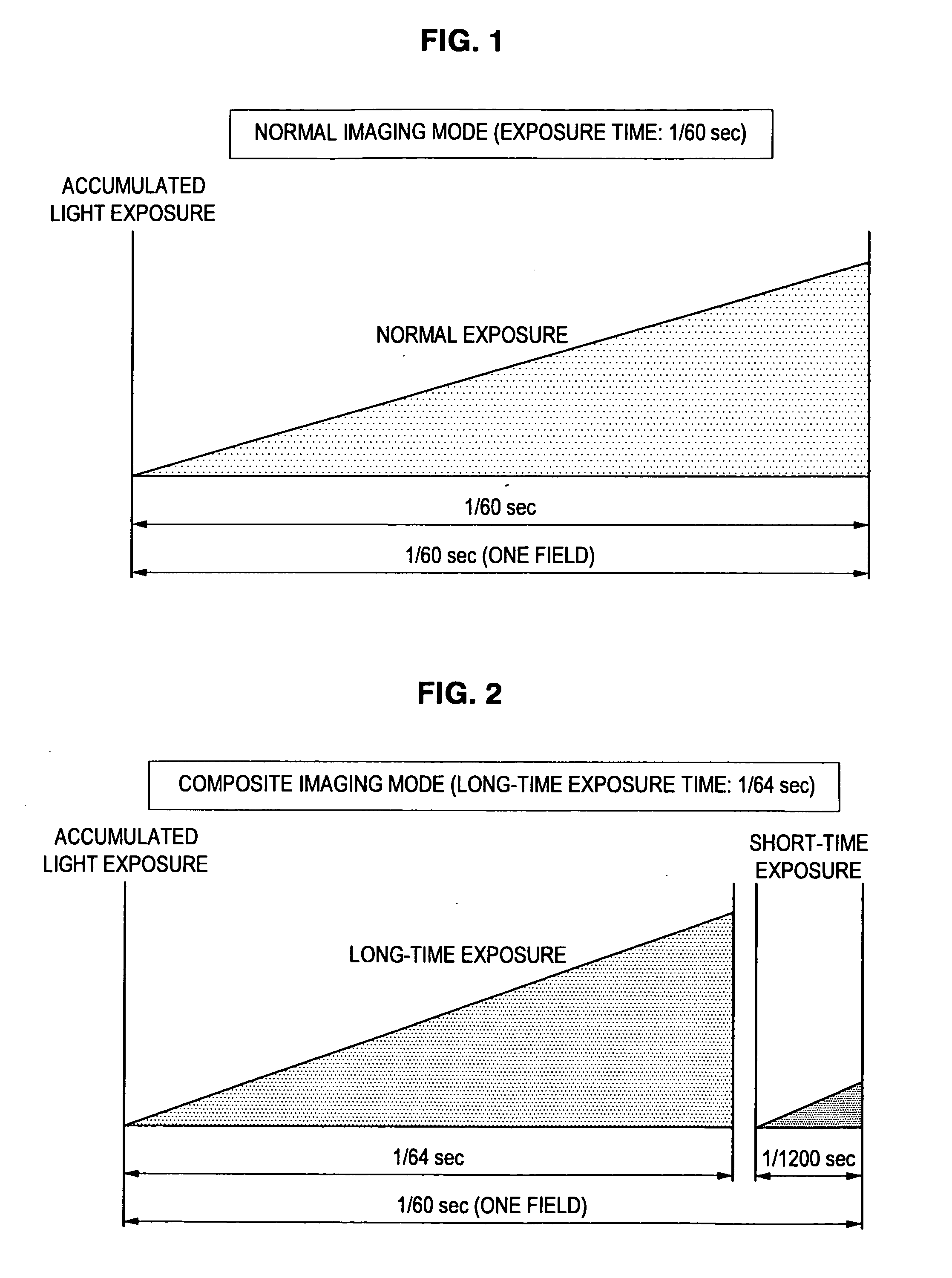
[0037]The description will be provided in the order shown below:[0038]1. Overview of imaging modes[0039]2. Overview of imaging mode switching and auto exposure control[0040]3. Configuration of the imaging apparatus[0041]4. Processing flow of imaging operations

[0042]An imaging apparatus and an imaging method according to an embodiment of the present embodiment will be described below. In the description that follows, a surveillance camera capable of picking up dynamic images is taken as an example of the imaging apparatus. However, the imaging apparatus according to the present invention is not limited to such...


PUM


Abstract

In an imaging apparatus capable of selectively performing an imaging operation in normal imaging mode and that in composite imaging mode, auto exposure control is stopped after the auto exposure control for long-time exposure image signals and short-time exposure image signals is temporarily completed in composite imaging mode and if, after the auto exposure control is stopped, a predetermined brightness change in images is detected continuously for a predetermined time or longer based on brightness values detected from the images obtained from a composite image signal, the imaging mode of the imaging apparatus is switched from the composite imaging mode to the normal imaging mode.

Description

CROSS-REFERENCE TO RELATED APPLICATION[0001]The present application claims priority from Japanese Patent Application No. JP 2008-271152 filed in the Japanese Patent Office on Oct. 21, 2008, the entire content of which is incorporated herein by reference.BACKGROUND OF THE INVENTION[0002]1. Field of the Invention[0003]The present invention relates to an imaging apparatus, an imaging method, and a program.[0004]2. Description of the Related Art[0005]In an imaging apparatus in related art using a solid image pickup device such as a CCD (Charge Coupled Device), the quantity of light (light exposure) input into the image pickup device is adjusted by an aperture or electronic shutter speed. That is, when a bright scene is imaged, adjustments are made to reduce the light exposure so that so-called “overexposure” should not occur by an output signal of the image pickup device being saturated. Conversely, in a dark scene, adjustments are made to increase the light exposure so that so-called “...

Claims


Application Information

Patent Timeline
Patent Type & Authority Applications(United States)
IPC IPC(8): H04N5/235G03B7/091H04N5/225H04N5/335H04N5/355H04N5/357H04N5/376
CPCH04N5/235H04N5/35581H04N5/2355H04N23/70H04N23/741H04N25/589
Inventor ASOMA, AKIRA
Owner SONY CORP
Why Eureka
Try Eureka