

Method for producing optical layered body, production apparatus of optical layered body, optical layered body, polarizer and image display device
a production apparatus and optical layer technology, applied in the direction of roads, instruments, traffic signals, etc., can solve the problems of whiteness or contrast on the image display face, light disturbs the displayed pixels, surface whitening or white cloud,
- Summary
- Abstract
- Description
- Claims
- Application Information
AI Technical Summary
Benefits of technology
Problems solved by technology
Method used
Image

Examples
example 1
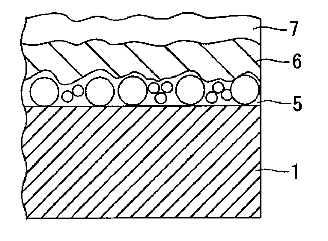
Formation of Under Coat Rough Surface Layer
[0392]Using a triacetyl cellulose film (TD 80U, manufactured by FUJIFILM Corporation) having a thickness of 80 μm as a transparent substrate, the composition 1 for an under coat rough surface layer was applied onto the film with a wire wound rod for coating (Mayer bar (metering coating rod)) #14, and the applied composition 1 was heated to dry for 1 minute in an oven of 70° C. to evaporate the solvent fraction, and then a coat was cured by irradiating the coat with ultraviolet light in such a way that an exposure becomes 30 mJ to form an undercoat rough surface layer.
Formation of Surface Adjustment Layer
[0393]Furthermore, the composition 1 for a surface adjustment layer was applied onto the under coat rough surface layer with a wire wound rod for coating (Mayer bar (metering coating rod)) #12, and the applied composition 1 was heated to dry for 1 minute in an oven of 70° C. to evaporate the solvent fraction, and then a coat was cured by irr...
example 2
Formation of Under Coat Rough Surface Layer
[0394]Using a triacetyl cellulose film (TD 80U, manufactured by FUJIFILM Corporation) having a thickness of 80 μm as a transparent substrate, the composition 4 for an under coat rough surface layer was applied onto the film with a wire wound rod for coating (Mayer bar (metering coating rod)) #14, and the applied composition 4 was heated to dry for 1 minute in an oven of 70° C. to evaporate the solvent fraction, and then a coat was cured by irradiating the coat with ultraviolet light in such a way that an exposure becomes 30 mJ to form an undercoat rough surface layer. Use of the fine particle, in which a difference in refractive indexes between the fine particle and the binder resin was up to 0.09, in the under coat rough surface layer made it possible to exert an internal diffusion effect and to prevent scintillation more effectively.
Formation of Surface Adjustment Layer
[0395]Furthermore, the composition 3 for a surface adjustment layer wa...
example 3
Formation of Under Coat Rough Surface Layer
[0396]Using a triacetyl cellulose film (TD 80U, manufactured by FUJIFILM Corporation) having a thickness of 80 μm as a transparent substrate, the composition 3 for an under coat rough surface layer was applied onto the film with a wire wound rod for coating (Mayer bar (metering coating rod)) #14, and the applied composition 3 was heated to dry for 1 minute in an oven of 70° C. to evaporate the solvent fraction, and then a coat was cured by irradiating the coat with ultraviolet light in such a way that an exposure becomes 30 mJ to form an undercoat rough surface layer. Use of the fine particle, in which a difference in refractive indexes between the fine particle and the binder resin was up to 0.09, in the under coat rough surface layer made it possible to exert an internal diffusion effect and to prevent scintillation more effectively.
Formation of Surface Adjustment Layer
[0397]Furthermore, the composition 3 for a surface adjustment layer wa...
PUM
| Property | Measurement | Unit |
|---|---|---|
| Length | aaaaa | aaaaa |
| Length | aaaaa | aaaaa |
| Length | aaaaa | aaaaa |
Abstract
Description
Claims
Application Information